Fellow DIYers:
The Martin Logan SL3 is a hybrid ESL with a 4 Ohm Vifa 10inch paper cone woofer crossed over at 250Hz 12dB/oct (according to manf) in a ~1.4 cu ft (~40 liters) sealed cabinet. I feel the bass isn't reaching its potential due to the passive XO. My ultimate plan is to go active XO with 4 channels of Pass DIY F5 (in progress).
I plan on doing this in steps:
A. Duplicate what the stock passive XO is currently doing by changing frequency-setting resistors in my (no laughing) Pyramid active XO;
B. Build a decent op amp-based active XO based on lessons learned in step A;
C. Build a Pass B1 buffer-based active XO and pre-amp based on lessons learned in step B.
I have already been told to just buy the Behringer DCX2496 and still might one day, as I'm sure it's the tool that I need. But I already have this other active XO, and my funds are currently going into the F5's I'm building. Plus, for now I kind of want to keep things analog and not limit myself to the ADC and DAC in the DCX2496. At the moment, I'm not planning to go active on the ESL section, as it has a passive crossover that also includes some EQ, and I don't feel this section is lacking relative to the bass.
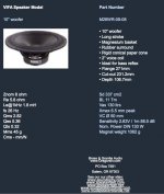
The bass XO consists of a 330uF Bennic electrolytic cap in parallel with a Vifa M26WO-06-04 woofer and a 5.3mH coil (1.1 Ohm DCR) in series with those. I haven't found the T/S parameters for this woofer, but I have found them for two other Vifa 10 inch woofers, the PL26WR-09-04 and M26WR-09-08 (see attachments). I would be surprised if my M26WO-06-04 is very different from the PL26WR-09-04.
So my first question for diyaudio's B&B is:
What is my passive bass XO doing? It doesn't seem to be a typical alignment. According to f=1/(2 pi C R), the 330uF cap seems to set 'f' at 120 Hz? So what is the 5.3mH inductor doing?
Thanks!
Tosh
The Martin Logan SL3 is a hybrid ESL with a 4 Ohm Vifa 10inch paper cone woofer crossed over at 250Hz 12dB/oct (according to manf) in a ~1.4 cu ft (~40 liters) sealed cabinet. I feel the bass isn't reaching its potential due to the passive XO. My ultimate plan is to go active XO with 4 channels of Pass DIY F5 (in progress).
I plan on doing this in steps:
A. Duplicate what the stock passive XO is currently doing by changing frequency-setting resistors in my (no laughing) Pyramid active XO;
B. Build a decent op amp-based active XO based on lessons learned in step A;
C. Build a Pass B1 buffer-based active XO and pre-amp based on lessons learned in step B.
I have already been told to just buy the Behringer DCX2496 and still might one day, as I'm sure it's the tool that I need. But I already have this other active XO, and my funds are currently going into the F5's I'm building. Plus, for now I kind of want to keep things analog and not limit myself to the ADC and DAC in the DCX2496. At the moment, I'm not planning to go active on the ESL section, as it has a passive crossover that also includes some EQ, and I don't feel this section is lacking relative to the bass.
The bass XO consists of a 330uF Bennic electrolytic cap in parallel with a Vifa M26WO-06-04 woofer and a 5.3mH coil (1.1 Ohm DCR) in series with those. I haven't found the T/S parameters for this woofer, but I have found them for two other Vifa 10 inch woofers, the PL26WR-09-04 and M26WR-09-08 (see attachments). I would be surprised if my M26WO-06-04 is very different from the PL26WR-09-04.
So my first question for diyaudio's B&B is:
What is my passive bass XO doing? It doesn't seem to be a typical alignment. According to f=1/(2 pi C R), the 330uF cap seems to set 'f' at 120 Hz? So what is the 5.3mH inductor doing?
Thanks!
Tosh
Attachments

Maybe the deafening silence was due to there being too much info given?
Simple question: What is this passive XO doing? 5.3mH inductor in series with (4 Ohm woofer // 330uF cap)?
Thanks!
Simple question: What is this passive XO doing? 5.3mH inductor in series with (4 Ohm woofer // 330uF cap)?
Thanks!
Tosh,
I suggest that you measure your speakers to find out what the response is. No one is likely to know accurately what the combined acoustic and filter response will be, and you are best to be sure. What you plan to do is half of an active xo, since there will only be active filtering on the woofer.
I suggest you try MiniDSP. It's a new option and looks very good. I'll be trying it myself when I get around to it. I also suggest that you try bypassing the passive xo and bi-amping.
Calibrated mic from cross spectrum labs + Behringer mini mixer + MiniDSP
then get measuring. That's a pretty low cost option and you can get right on it. If you feel that you must have an analogue then you can always develop it with MiniDSP. This approach will help you most in the design so that you can fully optimise it. You can always design it this way, then build your xo to suit what you've determined works best.
Keep in mind that active allows other options - why limit yourself to what your passive xo can do?
Tosh,
Paul has the right idea.
I think you should measure the electrical (not acoustic) responses of the existing filter sections so you have a very accurate baseline. No acoustic measurements are required so you can perform these tests using a differential (transfer function) measurement via a program like ARTA, or Spectraplus, or similar. (White or pink noise excitation.) The results of those tests will yield "target" curves that you can try to match with your active crossover implementation.......if you choose to do so. You could also start from scratch and try to better the existing design......but that's going to require some acoustic measurements.
Cheers,
Dave.
Why are you making this more complicated than it needs to be?
Your calculation is incorrect (it only applies for 1st order filters).
The L & C combine for a 2nd order lowpass at 250Hz, as described by the manufacturer.
That should be very straightforward to duplicate with an active filter. The beauty with active is that you'll be able to tune it (cutoff frequency and level) to suit your room.
Last edited:
Knowing Martin Logan, (Monolith owber) I would suggest that the first thing you try is to add impedance compensation across the woofer.
F = 1/(2Pi sqrt(LC)) = 120. That is corner frequency of the LC crossover. At that frequency it is likely that the actual filer is interacting with the driver resonanc epeak which can muddy up the bass.
F = 1/(2Pi sqrt(LC)) = 120. That is corner frequency of the LC crossover. At that frequency it is likely that the actual filer is interacting with the driver resonanc epeak which can muddy up the bass.
paulspencer and Davey:
Of course to create the ultimate active XO I would need measuring equipment, software, etc., and perhaps that will happen one day. For now, I just thought it would be pretty straightforward to duplicate the stock passive XO with my existing active XO and hear the difference.
Of course to create the ultimate active XO I would need measuring equipment, software, etc., and perhaps that will happen one day. For now, I just thought it would be pretty straightforward to duplicate the stock passive XO with my existing active XO and hear the difference.
If so, it's not a typical 2nd order ~250Hz low pass alignment. For example, plugging 240Hz (12dB/oct Linkwitz-Riley) and 4 Ohms into an online calculator does yield the 5.3mH inductor I have, but a capacitor of only 83uF (nowhere near as high as 330uF). Similar discrepancies for Butterworth and Bessel types...Why are you making this more complicated than it needs to be?
Your calculation is incorrect (it only applies for 1st order filters).
The L & C combine for a 2nd order lowpass at 250Hz, as described by the manufacturer.
This makes me suspect that the largish 330uF cap is creating a 6dB/oct knee in the XO quite a bit lower than 250Hz....?
Is it really as simple as plugging L and C into that equation? Seems that's not telling me the whole story.F = 1/(2Pi sqrt(LC)) = 120. That is corner frequency of the LC crossover. At that frequency it is likely that the actual filer is interacting with the driver resonance peak which can muddy up the bass.
In this Stereophile review they measure the woofer resonance at about 36Hz, which should be far enough away.
Is it really as simple as plugging L and C into that equation? Seems that's not telling me the whole story.
In this Stereophile review they measure the woofer resonance at about 36Hz, which should be far enough away.
Yes it is that easy, sort of. 1/(2PIsqrt(LC)) will give you the resonant frequency (corner) of the LC components but it will not tell you what Q is. Q will depend on the load. There will also be some effect of VC L on this as well.
36 Hz isn't that far away.
Here is a simulation of what I think is close to your woofer:

The green traces are what the electrical response of the crossover is without impedance compensation for the resonance peak at 36 Hz. The red traces are what happens if Z comp in added (series LRC across the voice coil). The Monolith had the same problem. Add the Z comp and that bass hump is gone and the bass then sounds balanced and more extended. W/o the Z comp, bass is muddy, and just plan a mess.
Update: I am using my Pyramid active xo set to 250Hz and 12dB/oct for the bass only (bypassing the stock passive bass xo), and it sounds very good. ESL is still using the passive XO and EQ.
Previously I had thought that the SL3's flimsy 3/4 inch MDF cabinet was contributing a large portion of the boominess, but most of this has gone away now, so I must conclude that the majority of the boom was due to the inductor causing the amplifier to lose control. And the amp and woofer are now working extremely well together, making tuneful low bass (and controlled cone excursions) I thought not possible from a 10 inch.
Moral: Don't put off going active on the bass!
- Status
- Not open for further replies.
- Home
- Loudspeakers
- Multi-Way
- Passive to active XO upgrade on ML SL3