Hey guys,
I want to implement passive time alignment to my passive 3 way xovers, doubts:
1-What's the correct position to calculate the delay:
a/ The middle of voice coils?
b/ The dust caps?
c/ The middle of the magnets?
2-What's the better solution:
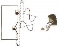
a/ Physical time alignment delay moving the tweeter & midwoofer to the same level as the woofer?
b/ Electrical time alignment delay using a phase shift added to the xover?
Attached pics of all that I seen on the net.
TIA
Felipe
I want to implement passive time alignment to my passive 3 way xovers, doubts:
1-What's the correct position to calculate the delay:
a/ The middle of voice coils?
b/ The dust caps?
c/ The middle of the magnets?
2-What's the better solution:
a/ Physical time alignment delay moving the tweeter & midwoofer to the same level as the woofer?
b/ Electrical time alignment delay using a phase shift added to the xover?
Attached pics of all that I seen on the net.
TIA
Felipe
Attachments
TM is right that the correct way is to measure with Holmimpulse or REW. The mechanical distances are not reliable indicators of the phase tracking of the drivers. Certain mixed crossover alignments can produce time and phase offsets. Look into "Quasi-Optimal" crossover designs. It is possible to add delay elements to the crossovers, but proper implementation is very difficult and complex. Zaph's ZD5 is one examplehttp://www.zaphaudio.com/ZD5.html url
I want to implement passive time alignment to my passive 3 way xovers, doubts:
1-What's the correct position to calculate the delay:
a/ The middle of voice coils?
b/ The dust caps?
c/ The middle of the magnets?
Any or none; this is a complex / variable condition that depends on driver design & use, so you're better off measuring if at all possible to establish the acoustic centre.
2-What's the better solution:
a/ Physical time alignment delay moving the tweeter & midwoofer to the same level as the woofer?
b/ Electrical time alignment delay using a phase shift added to the xover?
Since 'better' is also a floating point that depends on design specifics, either or neither. Not that it matters, by nature I'm inclined to always look for acoustic / mechanical solutions to acoustic / mechanical 'problems' first. However: physical time alignment, via a stepped or sloping baffle has its own issues, notably the potential for additional diffraction etc., and this can (can) get worse the larger the required offset. So a passive delay network, providing you have the data to do it, may sometimes reduce these compromises, while not being without some itself -notably the fact that they can be difficult to design (this can be overstated -the two I've done took a bit of work but no more) and require more components, increasing cost. YMMV.
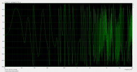
Attached phase measurement at the listening point, smoothing 1/6.
TM is right that the correct way is to measure with Holmimpulse or REW. The mechanical distances are not reliable indicators of the phase tracking of the drivers. Certain mixed crossover alignments can produce time and phase offsets. Look into "Quasi-Optimal" crossover designs. It is possible to add delay elements to the crossovers, but proper implementation is very difficult and complex. Zaph's ZD5 is one examplehttp://www.zaphaudio.com/ZD5.html url
Post 4 is the phase measured with ARTA.
Last edited:
I have measurements 50 cm from drivers & near field 2-3cms, what data do you need: FRD, ZMA & PIR (the las only for ARTA), also I have pics of measurements FR 50cm from drivers & near field of drivers. Drivers are:
Tweeter Seas Millenium
Mid-woofer Scan Speak 18W8545-00
Woofer SB Acoustic 8” SB23NRXS45-8
Tweeter Seas Millenium
Mid-woofer Scan Speak 18W8545-00
Woofer SB Acoustic 8” SB23NRXS45-8
Attachments
Last edited:
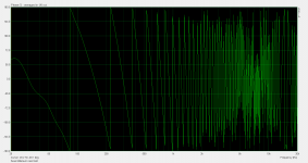
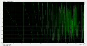
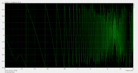
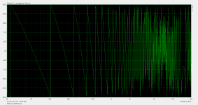
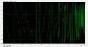
Attached pics with separate phase of each driver.
Attachments
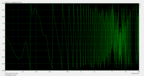
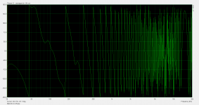
Attached phase measurement at the listening point, smoothing 1/6.
Pic post 4 is filtered with all drivers.
Looks like you have to read these instructions for ARTA users and study several different diy project "stories" from kimmosto, Krutke, Gravesen etc.
Then decide which design/simulation program you wil be using.
https://kimmosaunisto.net/Software/VituixCAD/VituixCAD Measurement Preparations.pdf
If you are planning a dsp-controlled system (Hypex FA, minidsp etc.) you can set delays by doing acoustic measurements and looking at impulse/step.
The acoustic center of sound radiation from a loudspeaker is a bit in front of a cone's dustcap and a bit behind a dome's top. But still only some coaxial drivers are "perfect" in this sense. The higher frequency xo we use, the more critical and difficult this gets. With only physical offset, we get in trouble off-axis...
Aligning by voice coils is just a broad advice for PA speakers which have a compression driver behind a horn, it doesn't suit for typical hifi speakers...
Last edited:
What program will you be using for the crossover simulation? You'll need to make gated measurements in ARTA to remove room interacrions. Here's a good explanation on how to make gated measurements in ARTA and also how to save minimum phase plots:
http://audio.claub.net/tutorials/FR%20measurement%20using%20ARTA.pdf
http://audio.claub.net/tutorials/FR%20measurement%20using%20ARTA.pdf
What program will you be using for the crossover simulation? You'll need to make gated measurements in ARTA to remove room interacrions. Here's a good explanation on how to make gated measurements in ARTA and also how to save minimum phase plots:
http://audio.claub.net/tutorials/FR%20measurement%20using%20ARTA.pdf
Thank you
I use Xsim http://libinst.com/Xsim/XSimSetup.exe XSim free crossover designer , attached Seas Millenium tweeter FRD files near field & 50cm, I did fine now?
Attachments
Last edited:
- Status
- This old topic is closed. If you want to reopen this topic, contact a moderator using the "Report Post" button.
- Home
- Loudspeakers
- Multi-Way
- Passive Time Alignment