I need the advice of an expert filter designer who is knowledgeable in passive ladder synthesis of filters with stopband zeros. I have some non-standard filters and would like to explore how they might be synthesized passively, pros and cons of trying that, etc. Examples of filters of this type are elliptic and Chebyshev filters. This would be for a passive, active, or actively-buffered passive line level non-commercial audio application. I am generally familiar audio filter design, although mostly for IIR digital loudspeaker crossover applications.
If you know your way around this topic (not just how to push buttons on a filter design program) I would really appreciate your time and advice. Please drop me a PM and I will explain more.
If you know your way around this topic (not just how to push buttons on a filter design program) I would really appreciate your time and advice. Please drop me a PM and I will explain more.
"I doubt if elliptic and Chebyshev can be made with a passive network..."
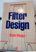
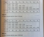
I found a book on one of my shelves, "Filter Design" by Steve Winder. It shows how to construct passive Chebyshev and passive Cauer ("elliptic") filters using resistors, inductors, and capacitors. So he thinks they CAN be made with a passive network. I have never done this myself. Never. But if someone paid me $4000 a day to read those chapters and use them to synthesize a filter, I suspect it would probably be successful.
Sorry for the awful image quality; I couldn't access a flatbed scanner today.
_
Attachments


Oh they certainly CAN! There is a HUGE book consisting of many, many design tables for ellitpical filters by Zverev. The problem is that all of these tables are for standard elliptical filters. I need to synthesize networks to realize filters that are LIKE elliptical filters in that they have zeros in the stopband but are NOT the standard ones found in these and similar tables.I doubt if elliptic and Chebyshev can be made with a passive network...
The best for me would be a software package (free is nice!) that allows me to enter the transfer function, or another way to describe the filter such as in terms of order, pole Q and frequency, and zero frequency. Then the software will spit out a passive network for me given the input and output impedances that I specify. Even if this is for lossless inductors and capacitors that would be OK.
If someone who is familiar with this sort of network synthesis and could chat I would appreciate it. I am trying to learn more about the level of complexity of this type of design, what are the pitfalls for audio applications, and other practical aspects of it. Please drop me a PM if that is you.
There are some serious problems using an active analog approach, which is why I need to look into a passive realization. This is particular to the low-pass form of the filter.The active reference I know of I posted here.
I never designed anything like that and I'm no filter synthesis expert, but if you know where you want the poles and zeros to end up, you could try something like this:
-Draw a ladder circuit with enough LC parallel and/or series tanks to make the zeros that you need
-Calculate the input impedance (symbolic calculation) of the LC filter including its termination resistor or resistors
-Calculate the characteristic polynomial; this is either the numerator or the denominator of the input impedance, depending on whether you drive the input with voltage or current
-From the desired poles, calculate the coefficients of the desired characteristic polynomial
-Equate the coefficients of the characteristic polynomial to their desired values and try to derive the component values from that
I have no idea whether the last step will lead to a useful analytical solution, or whether you get stuck there. The other steps are straightforward (but tedious).
If it doesn't work, read DeVerl S. Humpheries' book on filter synthesis very carefully and use whatever tricks he uses.
... Equate the coefficients of the characteristic polynomial to their desired values and try to derive the component values from that ...
I think you could do this pretty straightforwardly by using numerical optimization. Either the "Solver" built into Excel, or one of the optimization algorithms available in Python through the SciPy library.
I think you could do this pretty straightforwardly by using numerical optimization. Either the "Solver" built into Excel, or one of the optimization algorithms available in Python through the SciPy library.
Thanks! I found a copy of Zverev's book on eBay for USD 105, and this other very interesting book , also on eBay, for USD 23. Will have them in ten days.
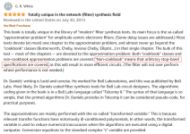
Note to @CharlieLaub -- the attached Amazon review of the $23 book, may perhaps suggest that it does what you want ...
_
Note to @CharlieLaub -- the attached Amazon review of the $23 book, may perhaps suggest that it does what you want ...
_
Attachments
Last edited:
There is an awesome book on filter design by H.G Dimopoulos - "Analog Electronic Filters Theory Design and Synthesis". See:
https://link.springer.com/book/10.1007/978-94-007-2190-6
It looks like there is an online copy that you can view here:
https://archive.org/details/fe_Anal...Synthesis_H._Dimopoulos_Springer_201/mode/2up
Using the methodology in Chapter 4 (starts on page 178 of the online copy at the archive.org link above) I can design any elliptic filter using only simple Excel worksheet formulas and have been doing lots of that. The next step is to realize the filter. I have been using IIR DSP for that but want to explore passive networks. There is some info on realization in this book that I should probably go back and take a closer look at, e.g. in Chapter 7: "Synthesis and Design of Passive Filters". I am not sure it is general enough for my needs.
Last edited:
And of course with analog filters the needed component tolerances become tighter, perhaps much tighter (as in much less than 1%) as the number of poles and zeroes goes up. Spice sims are easy enough, but getting real components with close enough value, not so much. I foresee putting carefully measured parts in series and parallel to get close enough values. For faster prototyping, put your measured parts values into the spice simulation to see the response you get.
For buying books online, I use this metasearch site - Amazon is not always the lowest price, and geez these books can get expensive:
http://bookfinder.com
For buying books online, I use this metasearch site - Amazon is not always the lowest price, and geez these books can get expensive:
http://bookfinder.com
If you are actively buffering you can split any filter upto into biquad sections making design much simpler - the full ladder topology has pretty gnarly algebra to map between component values and pole/zero positions and vice versa as the number of components rises. A single biquad (2nd order) section (ie RLC) is mathematically much more tractable, you simply assign one pair of poles or zeroes to each biquad and separate them with buffers.
There are also expressions for component sensitivity which is another set of algebra to wade through - again much more tractable on a biquad section - ie you can answer the question "does this component need to be 1% or will 2% be good enough"...
And its easy to switch from RLC to Sallen-Key active stages this way too.
A fully passive RLC ladder has no issues with headroom, but the imperfections in real inductors will be a limitation, and you need the design equations somehow. Or you can simulate and play around with component values by trial-and-error - time consuming but probably quite instructive - each component value has an effect on every pole so there's a risk of chasing round in circles!
@CharlieLaub It's free, but requires a little effort .
- Octave's system synthesis in the signals package (invfreqs) can fit a n-th order polynomial to the arbitrary FRD (freq, mag, phase) that you provide.
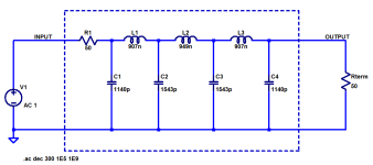
- then you need to pick a network synthesis strategy Network Synthesis (skip to page 16,17) to see an example. Realized as RLC ladder networks.
- the synthesis process requires poly division, which can also be done by Octave (deconv)
- the circuit you created can be checked in Octave's Spice simulator (OCS) to close the design loop
If you are actively buffering you can split any filter upto into biquad sections making design much simpler - the full ladder topology has pretty gnarly algebra to map between component values and pole/zero positions and vice versa as the number of components rises. A single biquad (2nd order) section (ie RLC) is mathematically much more tractable, you simply assign one pair of poles or zeroes to each biquad and separate them with buffers.
There are also expressions for component sensitivity which is another set of algebra to wade through - again much more tractable on a biquad section - ie you can answer the question "does this component need to be 1% or will 2% be good enough"...
And its easy to switch from RLC to Sallen-Key active stages this way too.
A fully passive RLC ladder has no issues with headroom, but the imperfections in real inductors will be a limitation, and you need the design equations somehow. Or you can simulate and play around with component values by trial-and-error - time consuming but probably quite instructive - each component value has an effect on every pole so there's a risk of chasing round in circles!
The filter type that I need to implement is the highpass or lowpass form of the notch (bandstop) filter. Please see this pdf for more info:
https://www.analog.com/media/en/training-seminars/tutorials/MT-210.pdf
These filters could be implemented via second order filter circuit or general biquad filter and are building blocks of e.g. elliptic filters. The overall filter is a cascade of second order sections, plus a first order section if the filter is odd.
Since starting this thread I have continued to check into analog active filters. Back about 10 years ago before I got into DSP I acquired a bunch of textbooks on filter design and created a few design tools. I went back and took a look at these last night and for the most part the transfer functions include a gain factor that makes it possible to avoid some of the gain problems that would occur when the standard LP-notch transfer function is used. I guess I had forgotten about that, since at the time I was not all that concerned about gain issues.
I would still like to find a simple and straightforward passive network that I could buffer. For example, if I could come up with a passive LC network with closed-form design equations that was able to implement a 2nd order lowpass or highpass notch I could buffer in between these just like with the active filters. Not exactly "passive" when buffered, but it's another synthesis approach without feedback. Maybe since it is only a second order network that would be possible? I could provide the design equations for the normalized filter and then the user can frequency scale it, or the like. This is for a paper on filter design that I am slowly creating, so it cannot be a nebulous or drawn out procedure such as a ladder type LC filter that would implement the entire Nth order transfer function. The application is envisioned to always be for line level filtering, not speaker level.
Then there is the possibility of designing the complete filter with a passive ladder and then implementing the inductors actively. This just seems like way too much time investment when there are easier ways to go about it.
Last edited:
This is a second-order filter with a notch and a high-frequency gain that's smaller than the low-frequency gain. It's not nice, because of the capacitive load on the input voltage source. With a nonzero source impedance, it becomes third order. Replace the inductors with capacitors and the other way around and the low-frequency gain is smaller than the high frequency gain (and the voltage source is shorted at 0 frequency instead of in the limit for frequency tending to infinity).

Using duality and reciprocity, you can come up with a bunch of variants. The one on the right looks more practical than what I had before; it needs two inductors, but at least the source isn't shorted anymore.

@MarcelvdG I don't know what this is that you invented, but the form of the transfer function is incorrect for a notch filter. There should not be an "s" term in the numerator for a notch filter. See Equation 9 of this pdf for the correct transfer function:
https://www.analog.com/media/en/training-seminars/tutorials/MT-210.pdf
Also, the correct response shape is shown in Figure 4.
https://www.analog.com/media/en/training-seminars/tutorials/MT-210.pdf
Also, the correct response shape is shown in Figure 4.
There isn't. The filter of post #16 has an s term in the numerator of the input impedance, which (under voltage drive) is the denominator of the transfer from input to output (a.k.a. the characteristic polynomial).
OK, I see my mistake, that wasn't the transfer function! I'm not used to describing filters in that way. It's a completely foreign language, all this stuff with passive filters via impedances and admittances and so on. I am used to describing filters by their transfer function parameterized via Qpole, Fpole (or Wpole), Fzero (or Wzero), and gain, or also possibly via the coefficients of the transfer function polynomials. All of the filters that I have developed and want to write about are described in that way, so it seems very cumbersome to try and use this other way to describe filters that is typically used for passive networks.
Perhaps I will just throw in the towel with passive networks and only mention that is is possible to realize these filters with that sort of filter embodiment. I am not sure a DIY would ever go to the trouble of designing and optimizing a speaker level passive ladder. The idea of actively buffered passive networks is just a more difficult way to do what I can already do via analog active circuitry, so that doesn't seem to be very worthwhile.
Perhaps I will just throw in the towel with passive networks and only mention that is is possible to realize these filters with that sort of filter embodiment. I am not sure a DIY would ever go to the trouble of designing and optimizing a speaker level passive ladder. The idea of actively buffered passive networks is just a more difficult way to do what I can already do via analog active circuitry, so that doesn't seem to be very worthwhile.
- Home
- Source & Line
- Analog Line Level
- Passive LC ladder filter synthesis - I need to chat with an expert!