For a passive solution, instead of just a resistor, why not use a DAC I/V transformer. It should do an even better job. Get that DAC to see a as close to 0 ohm impedance as possible...
Brian,
I thought even for the DAC transformer you need a resistor on the DAC output to develop the input voltage for the transformer?
Jan Didden
I thought even for the DAC transformer you need a resistor on the DAC output to develop the input voltage for the transformer?
Jan Didden
Re: Very interesting
😀 😀 😀
Bernhard said:It shows that @ -60 dB a 20bit DAC is not better than the good old TDA1541.
😀 😀 😀
janneman said:Brian,
I thought even for the DAC transformer you need a resistor on the DAC output to develop the input voltage for the transformer?
Jan Didden
Correct, but, the a current out DAC really performs best with a 0 ohm load. Otherwise, use a voltage output DAC.
This is the point of the electronic IV stages trying to ge that magical 0 ohm load with enough gain & minimal noise.
Now, using a transformer & 5 ohm resistor, example setup, the load on the DAC with resistor may be 5 ohms & the output wil be a puny .1v, but on the other side with a gain of 10x, you will have your 1v rms.
The idea here is the transformer shrinks your 100 ohm DAC load, which is crummy for the DACs current switches making an un-optomized circuit, to 5 or less ohms, then it passively gives you the gain.
Here is my favorite IV stage transformer:
http://www.sowter.co.uk./specs/9762.htm
(how's that for a flat wideband transformer)
I don't quite understand the engineering issues in a transformer based I/V.
The transformer you quote has a DCR of 6 Ohms. In that case could one not do without the I/V resistor altogether?
And: does the transformer really "shrink" the I/V resistor's value? Would the effective input impedance of a transformer not depend on the load impedance of the transformer at its secondaries? So, if you have this transformer with a 6.5:1 turns ratio and a load of 10k on the secondaries, would the effective input impedance not be 10000/6.5=1.5k? In that case, would it not rather look like you still do need a fairly small I/V resistor OR a small load? Or do I misunderstand this and the load recommended in this site, 100-200 Ohms, is to be placed at the secondaries only?
Example, no I/V resistor at DAC, DCR 6 Ohms, secondaries load of 39 Ohms, would you not get 39/6.5=6, + 6 Ohms DCR Ohms = 12 Ohms effective primaries impedance? That being close to the maximum load a typical current output can drive, if we leave it at that, we get 16 dB voltage gain, or 0.15 V output, which is quite OK indeed. With a 200 Ohms load on the secondaries and no load on the primaries, we'd have 30 Ohms on the primaries, may still be OK. So, assuming no resistor at the DAC side, I can see how this works. I just can't figure out how this works with a 100 Ohms load on the DAC and a highish load on the secondaries.
And - for unipolar current outputs, what to do with the DC through the transformer? Put a beefy electrolytic at the DAC ouput? or will the transformer tolerate the say, 2 mA of a TDA1541 (through 6 Ohms DCR that is just 0.024 mW, but what about saturation?)
Konnichiwa,
There is nothing to understand nor are there any issues. A transformer does not convert Current to Voltage.
Nope.
Yes, a transformer transforms the impedance by the square it's winding ratio. And it will transform the current or voltage by the winding ratio (voltage up current down for stepup transformers).
In other terms, if you have a DAC with an Output current of +/-1.2mA for full scale and you apply this current to the primary of a 1:10 Transformer you will give +/- 120uA on the secondary. To get a 5.65V Peak Peak signal from this current you need around 23k5 as I/V resistor. This 23k5 will be transformed into the transformers primary by the square of the 1:10 winding ratio, namely 100. So the load reflected upon the DAC's current output is around 235 Ohm.
Clearly, an output impedance of 23KOhm is impractical, so if we follow the Transformer plus I/V resistor with an active stage we can reduce the I/V resistor.
Let's use a 6922 as Valve for the analogue stage. It has a gain of around 29db with a 22k Anode load and around 3K output impedance. For 2V RMS (5.65V P-P) from the Anode we need around 200mV P-P or 100mV Peak. So we require 100mV from 120uA or 833 Ohm. Let's use 1k for arguments sake, so we require a 1:10 transformer that can be loaded with 1k and this will then reflect an impedance of 10 Ohm plus all direct current resistive losses.
While looking good on paper this is not a very practical transformer to find of the shelf, so we are back to first converting our current to Voltage with a suitable resistor (say 10 Ohm) and then stepping it up with a traditional 1:10 Stepup Transformer (for microphones and or MC Pickups) loaded with it's usual secondary load (say 10k giving a 100R Load in parallel with the 10R I/V conversion resistor) to give use 100mV Peak from the DAC's output into our Valve stage.
This does not work easily for unipolar DAC's. You will need a suitable offset voltage in the "middle" of the linear range which has a zero AC impedance (or at least a fairly low and consistent AC impedance).
If it is designed suitably it will be fine. I took a different take in my Adagio. The transformer used had a DCR of the primary of 180 Ohm and I used a 20 Ohm I/V resistor. This way only a very small offset went into the transformer, one I tested to have no material negative effects. If you have a low DCR primary transformer you can simply use a series resistor.
BTW, with the TDA1541 the best solution I found is no transformer and a rather tricky near "zero bias" implementation of the 7308/E88CC which uses a rather higher than usual value I/V conversion resistor (100R). Just one resistor, one RLC combo for compensating the sinc treble rolloff, one valve, one anode resistor and one output coupling capacitor.
Sayonara
MBK said:I don't quite understand the engineering issues in a transformer based I/V.
There is nothing to understand nor are there any issues. A transformer does not convert Current to Voltage.
MBK said:The transformer you quote has a DCR of 6 Ohms. In that case could one not do without the I/V resistor altogether?
Nope.
MBK said:And: does the transformer really "shrink" the I/V resistor's value?
Yes, a transformer transforms the impedance by the square it's winding ratio. And it will transform the current or voltage by the winding ratio (voltage up current down for stepup transformers).
In other terms, if you have a DAC with an Output current of +/-1.2mA for full scale and you apply this current to the primary of a 1:10 Transformer you will give +/- 120uA on the secondary. To get a 5.65V Peak Peak signal from this current you need around 23k5 as I/V resistor. This 23k5 will be transformed into the transformers primary by the square of the 1:10 winding ratio, namely 100. So the load reflected upon the DAC's current output is around 235 Ohm.
Clearly, an output impedance of 23KOhm is impractical, so if we follow the Transformer plus I/V resistor with an active stage we can reduce the I/V resistor.
Let's use a 6922 as Valve for the analogue stage. It has a gain of around 29db with a 22k Anode load and around 3K output impedance. For 2V RMS (5.65V P-P) from the Anode we need around 200mV P-P or 100mV Peak. So we require 100mV from 120uA or 833 Ohm. Let's use 1k for arguments sake, so we require a 1:10 transformer that can be loaded with 1k and this will then reflect an impedance of 10 Ohm plus all direct current resistive losses.
While looking good on paper this is not a very practical transformer to find of the shelf, so we are back to first converting our current to Voltage with a suitable resistor (say 10 Ohm) and then stepping it up with a traditional 1:10 Stepup Transformer (for microphones and or MC Pickups) loaded with it's usual secondary load (say 10k giving a 100R Load in parallel with the 10R I/V conversion resistor) to give use 100mV Peak from the DAC's output into our Valve stage.
MBK said:And - for unipolar current outputs, what to do with the DC through the transformer?
This does not work easily for unipolar DAC's. You will need a suitable offset voltage in the "middle" of the linear range which has a zero AC impedance (or at least a fairly low and consistent AC impedance).
MBK said:or will the transformer tolerate the say, 2 mA of a TDA1541 (through 6 Ohms DCR that is just 0.024 mW
If it is designed suitably it will be fine. I took a different take in my Adagio. The transformer used had a DCR of the primary of 180 Ohm and I used a 20 Ohm I/V resistor. This way only a very small offset went into the transformer, one I tested to have no material negative effects. If you have a low DCR primary transformer you can simply use a series resistor.
BTW, with the TDA1541 the best solution I found is no transformer and a rather tricky near "zero bias" implementation of the 7308/E88CC which uses a rather higher than usual value I/V conversion resistor (100R). Just one resistor, one RLC combo for compensating the sinc treble rolloff, one valve, one anode resistor and one output coupling capacitor.
Sayonara
Thanks, makes sense. Some misunderstandings along the way but nevermind (I didn't assume that transformers convert current to voltage just by themselves, the "I/V resistor" needs to exist at some point - however the question was whether it needs to be on the primary).
The square relation of the windings is one of the points I had missed... must be of course because power in must correspond to power out (minus losses).
Looks like it could work with a fairly simple setup. The TDA1541 should lend itself to a Pass D1 style I/V as well, but that is more complex to get zero bias reliably.
I now have a JFET and op amp based solution, I wanted to give a transformer a try, also because of inherent RF rejection.
MBK said:\
I now have a JFET and op amp based solution, I wanted to give a transformer a try, also because of inherent RF rejection.
DONT FORGET the voltage isolation!!!!!!!!
At times, it's unbelievable how useful this can be, especially if you want to convert unbalanced dacs to a true unbalanced output, or, feed a simple balanced line stage SOZ type of buffer running on the same psp without any DC reg caps at all in the audio path.
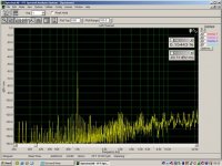
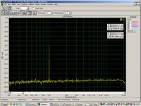
-60dB plots....
I am disturbed about the -60dB dumps.
I started a new series of tests playing with bit dephts and another data source ie the DAC Tester that was kindly provided by ULAS on the forum and a Sony CDP.
All pics are spdif direct.
First out is a SONY CDP 16/44....
I am disturbed about the -60dB dumps.
I started a new series of tests playing with bit dephts and another data source ie the DAC Tester that was kindly provided by ULAS on the forum and a Sony CDP.
All pics are spdif direct.
First out is a SONY CDP 16/44....
Attachments
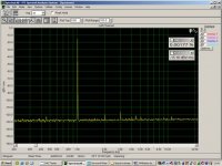
Could it be that compared to the -70dB signal, with -60dB there are more bitd switching in the DAC chip and those extra switching bits are bad by accidant in the Sony ?
Thx Pedja,
I tried to burn these files but the program states they are the wrong format!?
Any idea as to why I can not burn them?
Also, looking at your pics I see similar hash on the non dithered signals.
Could it be that the "hash" only shows when analyzing 16 bit non-dithered data on a 24 bit processing system?
A 8, if that may help, you can download both dithered and undithered, 0dB and -60dB sine signals (.wav files) from here and burn by yourself to CD. You have there all the files analyses as such, so you can know what you are working with.
I tried to burn these files but the program states they are the wrong format!?
Any idea as to why I can not burn them?
Also, looking at your pics I see similar hash on the non dithered signals.
Could it be that the "hash" only shows when analyzing 16 bit non-dithered data on a 24 bit processing system?
I did not encounter any problem. What program do you use to burn them?A 8 said:I tried to burn these files but the program states they are the wrong format!?
Any idea as to why I can not burn them?
That hash is the regular part of the conventionally generated signal. That’s why dither. The difference can be seen normally on 16 bit system.Also, looking at your pics I see similar hash on the non dithered signals.
Could it be that the "hash" only shows when analyzing 16 bit non-dithered data on a 24 bit processing system?
Pedja
Its a HP burner and I use whatever came with it; HP CD writer powered by veritas.I did not encounter any problem. What program do you use to burn them?
I've checked the files on my Xp laptop and they are indeed 16/44 but only one channel...perhaps thats why.
Yes, these are the mono files. Work normally with Nero so I did not expect it can be the problem. The brief check says EAC or even Windows Media Player 8 (XP) can burn them too.
- Status
- Not open for further replies.
- Home
- Source & Line
- Digital Source
- Passive I/V vs. traditional I/V, FFT pics.