> slight fear of TIM.
Oh, don't be afraid of TIM. A little slew-limiting sometimes "improves" sound. And most low-feedback designs, and most designs with gain compensated for that gain, are unlikely to ever hit bad TIM.
> What is really the sound of amplifier having TIM?
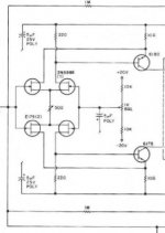
Try it. Build this:
The LM301 is externally compensated. I put it in a circuit with gain of 3 and a 3:1 loss pad in front for overall unity gain.
For LM301 at gain of 3, the suggested compensation cap is about 10pFd, the slew rate is about 2V/µSec.
Put this between your preamp and your power amp. The peak signal level there is around 2V. Jung's early listening tests suggest that it works out that if your slew rate in V/µSec is greater than your peak signal voltage, audio passes cleanly. Common sense suggests that, on most real music, much lower slew rates won't nick the audio.
So with just the 10pFd the slew rate is adequate to avoid TIM on audio signals. (If your source has strong supersonic signals, like a leaky FM tuner or a moving-coil cartridge with a phono preamp that goes flat above 50KHz, fix it.) The LM301 is not a fabulous chip, but within its limits it doesn't suck so bad. And I'm trying to demonstrate gross TIM, not subtle effects.
Now use the DIP switch to switch-in additional compensation capacitance. 300pFd should be noticable on strong treble. 3,000pFd could turn everything to mush, treble splattering all over the audio band.
Oh, don't be afraid of TIM. A little slew-limiting sometimes "improves" sound. And most low-feedback designs, and most designs with gain compensated for that gain, are unlikely to ever hit bad TIM.
> What is really the sound of amplifier having TIM?
Try it. Build this:
An externally hosted image should be here but it was not working when we last tested it.
The LM301 is externally compensated. I put it in a circuit with gain of 3 and a 3:1 loss pad in front for overall unity gain.
For LM301 at gain of 3, the suggested compensation cap is about 10pFd, the slew rate is about 2V/µSec.
Put this between your preamp and your power amp. The peak signal level there is around 2V. Jung's early listening tests suggest that it works out that if your slew rate in V/µSec is greater than your peak signal voltage, audio passes cleanly. Common sense suggests that, on most real music, much lower slew rates won't nick the audio.
So with just the 10pFd the slew rate is adequate to avoid TIM on audio signals. (If your source has strong supersonic signals, like a leaky FM tuner or a moving-coil cartridge with a phono preamp that goes flat above 50KHz, fix it.) The LM301 is not a fabulous chip, but within its limits it doesn't suck so bad. And I'm trying to demonstrate gross TIM, not subtle effects.
Now use the DIP switch to switch-in additional compensation capacitance. 300pFd should be noticable on strong treble. 3,000pFd could turn everything to mush, treble splattering all over the audio band.
Hi, PRR,
Thanks for the cct. I will try it, to hear what is TIM looks like.
This is the pleasant answer.
Thanks for the cct. I will try it, to hear what is TIM looks like.
Oh, don't be afraid of TIM. A little slew-limiting sometimes "improves" sound
This is the pleasant answer.
Hi, Mr. Pass,
The drain output comes from common base=folded cascode front end, like the x100backengineered.------X600 and x1000 uses folded cascod+susy patent
The drain output comes from common source=ordinary 3 stages amp? (differential, VAS, current output)? I cannot think of other VAS configuration that the signal comes to the base, emitor tied to the rail, besides ordinary/old fashioned design.-----smaller X amp uses conventional 3stages amp+susy patent?
This is also important hint, wheter the outputs are in the feedback loop or not.
and the full voltage swing comes off a Drain of a transistor (which you can call a VAS), but this Drain can be from
a device operated either as Common Source or Common Gate.
The drain output comes from common base=folded cascode front end, like the x100backengineered.------X600 and x1000 uses folded cascod+susy patent
The drain output comes from common source=ordinary 3 stages amp? (differential, VAS, current output)? I cannot think of other VAS configuration that the signal comes to the base, emitor tied to the rail, besides ordinary/old fashioned design.-----smaller X amp uses conventional 3stages amp+susy patent?
The later circuits we deem more appropriate for amplifiers where we have chosen to include the output stage in the loop, although it's perfectly suitable for the case where it is not.
This is also important hint, wheter the outputs are in the feedback loop or not.
I see that you will hound me until I deliver more hints.
The input stage of the X150 - 350 is a dual differential JFET
input feeding quad-symmetrical common emitters. These have
been degenerated at the JFET outputs and the emitters until we
get the same transconductance for the whole as the original
folded cascode MOSFET circuit, which had a transconductance
of about .05 Siemens.
Surprise surprise!!
I always tought passlabs using Mosfets for differential, especially TO-220 size. I see Jfets only in ONO. It is true, every master can make good things with everything.
Jfets have low voltage. Cascode is a big chance here.
Got 2 more question.
1. Full complementary Jfets (K389-J109) can use 2 way of biasing. One is with CCS or resistor load, two is with stacking each other (like Mr.Curl likes to use them). Which is the one in smaller Xamp?
2. Is there any "Magic Resistor" involved?
*Mr. Pass, I forgot the "s" in nelson@passlabs.com, so I resend the email. Any comment?*
lumanauw said:Jfets have low voltage. Cascode is a big chance here.
1. Full complementary Jfets (K389-J109) can use 2 way of biasing. One is with CCS or resistor load, two is with stacking each other (like Mr.Curl likes to use them). Which is the one in smaller Xamp?
2. Is there any "Magic Resistor" involved?
The JFETs are cascoded.
The JFETs are biased with resistors.
I need a definition of magic resistor, but the Sources of the
differential JFETs are directly connected.
I need a definition of magic resistor, but the Sources of the differential JFETs are directly connected.
The sources of Jfets are directly connected. It means no Re here.
Mr.Pass, what I mean by magic resistor is the definition I borrowed from the alephx thread. The resistor from both the outputs to the junction of emitors of differential (to help DC offset). IF this full complementary design uses such a "Magic Resistor", will there be 4 of them? (while in alephx there is only 2 of them)
The JFETs are biased with resistors.
Mr. Pass, what is your personal thinking of stacking mosfets (Like Mr. Curl likes to do it)? What is the pro and cons than having CCS or R load?
Just think of something.
We are talking about X configuration here. If the Jfets differential having no Re, just tied together, would it stable just to bias it with Resistor? There is no Re, shouldn't it be CCS instead of R loading to get matched operation? (example, if the amp is driven by single ended input, not balanced input). Or I miss something?
The JFETs are biased with resistors.
the Sources of the differential JFETs are directly connected
We are talking about X configuration here. If the Jfets differential having no Re, just tied together, would it stable just to bias it with Resistor? There is no Re, shouldn't it be CCS instead of R loading to get matched operation? (example, if the amp is driven by single ended input, not balanced input). Or I miss something?
You are missing something. The dual pairs of Matched JFETs
are self biasing (in the manner taught by Curl) and are not
biased on their Sources with anything except a single resistor
to set the overall current. The output bias resistor (one for
each JFET drives the Common Source level shifters.
are self biasing (in the manner taught by Curl) and are not
biased on their Sources with anything except a single resistor
to set the overall current. The output bias resistor (one for
each JFET drives the Common Source level shifters.
Thanks Mr.Pass for the answer. It answers 2 things. The Jfets are self biased to each other like Mr.Curl used to.
Also if the configuration is like this, there cannot be any "Magic Resistor" Involved.
In the alephX theread there is problem with DC offset, so it comes "Magic Resistor". Does your small X amp using other kind of DC stabilizer? Servo?
Is the level shifter (VAS) mosfets ? If N and P mosfets are used, the resistor in the leg of differential cannot be the same, because they have slight different Vgs, between N and P type (just like A75, the resistors can be adjusted by VR or have different fix value)?
Mr. Pass, in your personal opinion, is there any merit of this configuration (stacking fets, because they have negative Vgs), instead of biasing them with CCS to rails?
One more question. Why I hardly find your design with Bipolar transistor (in differential or final stage)?
Attachments
At the rate you're going it would be more efficient to simply ask Nelson for a full schematic of the X amplifier.
I've got two separate ideas in mind as to how to arrange a single pair of 'magic resistors' to do the trick, but until I get some parts in I can't check to see if either works.
Knowing Nelson, it's unlikely that he's using a servo.
It seems rather unlikely that he would use self-biased complementary differentials if he didn't think that the topology had merit. JFETs have less noise than MOSFETs or bipolars and the 2SK389/2SJ109 duals offer a nifty way to get FETs that are fairly well matched and will track together thermally. Biasing with a current source to the rail works--Nelson did so in the A-75, for instance--but this is more elegant.
His older designs are chock-full of bipolars. My Threshold S-500s have quite a few. But bipolars tend to lend themselves to circuits with high gain. The high gain, in turn, needs to be gotten rid of. That implies high rates of negative feedback, which brings along unpleasant baggage as far as sound quality. MOSFETs also tend to be easier to work with, thermally.
Grey
Grey,
Do you think Mr.Pass will give the sch, since the amp is still in production? I will try anyway.
I want to ask you a question. In full complementary X design, what happens if we put current mirror in top and bottom of both the differential legs? Will the cct work at all? Current mirror acts to balance current in both legs. If we use both legs for audio signal, would current be imbalance in purpose, to drive each side of X amp?
Or if we put these current mirrors, the X cct still works and DC becomes better?
X amplifier schematic is not available for public, since the amp itself is still in production. This is the answer I got from Mr.Pass.
Thanks anyway, Mr.Pass
Thanks anyway, Mr.Pass
lumanauw said:
I've made a simple experiment, about placing Re or jumper it. Re is 100ohm. The result, with Re the sound is dull, without Re, the sound is more detailed. That is why I ask this question. To me, without Re is better sound. But reading leach paper it gives me a slight fear of TIM.
....
What is really the sound of amplifier having TIM?
Is this "Re eliminating" can be applied also in VAS? I see in A40, Mr. Pass do not use Re in the VAS transistor. If I want to eliminate Re in VAS transistor, assuming the Vbe is 0.65V, what is the voltage drop in the differential collector resistor? Should it be more than 0.65V or less than 0.65V?
OK, TIM and Re and VAS design, a lot of concepts. At the heart is TIM, but I'd like to sort of unravel the tangle of ideas here.
ABOUT Re: You might not understand why designers choose to "add Re" to input pairs. Here is my understanding of the usual reasons.
The main reason to add modest Re's to the input pairs is to match the trasistors, even if they are not matched pairs. Ideally, you would not need to do this, because you would use a matched dual transistor, on the same die and thermally coupled in the same package. But if these are too expensive, or if you need higher voltage rating than available dual transistors (60v max), then you use unmatched parts and depend on a small Re to equalize them. When you see Re in the range of 22-68 ohm, probably the intent is to equalize the pair.
When you go to higher Re, you are intending something else: trading transconductance for linearity of the input pair. Leach makes this point very clearly, as does Self. Using no Re, the linear range is typically +-57 mv. Using a 100 ohm value, the range is +-200mv. Using Leach's 300 ohm Re, the input differential voltage range for linear operation is +-1v, extremely wide.
Why would you want to do this? Because you want to avoid input overload, which sounds bad no matter what label you give it. Basically, it stops the music for a time. For example, after a sharp sound like a loud snare drum, you would not hear vocals for short but audible interval.
Here is how this works: If you drive the input with a rapidly rising signal, there is a delay through the stages of an amplifer to the output. The negative feedback signal from the output will be delayed, causing a large input differential voltage to the input pair for a time -- until the output reacts and the feedback signal returns. This interval is when the input pair can overload (and cease to pass signal because it's maxed out already). You don't want it to ever overload because it blocks the music during that time, until the input stage recovers (either because the input signal falls or the output catches up with the signal).
So now we recognize a problem, how do we solve it? There are many techniques for preventing input overload. One is to "add Re" to the input pair, to get a wider linear range. A second is to put passive filters on the amp input, to limit risetimes. (That is very good practice, because other circuits, such as the VAS, are also likely to overload.) A third is to use "lead compensation" from the VAS to give an earlier negative feedback signal to the input stage.
Leach used all three of these techniques. Pass used the input filter and lead compensation in the A40. Both work well, designer's choice. I can overload either amp with an artificial test signal (not real music), so we're talking about a matter of degree of resilience to overload.
ABOUT TIM: You asked "What is really the sound of amplifier having TIM?" It's a catch-all term for a lot of different distortions related to handling transients in the music. It doesn't have any one sound, because it's a label for a collection of bad effects from poor handling of transients. Some early solid state designs had excellent measured performance, using the steady-state metrics of THD and IM, but sounded bad on transients. Some amps blocked, which merely sounds dreadful, but some burst into oscillation when overloaded (which could be destructive).
To quantify these effects, in the early 70s audio engineers labelled the collection of effects TIM and developed new tests to measure it (Dynamic Intermodulation Modulation "DIM"). DIM is measured using a low frequency, higher amplitude square wave mixed with a high frequency sine wave (specifically, 3.18 kHz square wave, 15 kHz sine wave, mixed 4:1, amplifed and spectrum analyzed, distortion products measured in %). Because designers became aware of TIM and because it could be measured, it could be avoided -- with additional care in design.
As is the way of things, TIM was overemphasized in the 70s, then became passe. But because the most excitement in music is in the transients, it's still important to handle them accurately. You can introduce TIM at any stage of an amplifer, so it's important to keep it in mind throughout the design.
Hi, Slowhands,
Thanks for the explenation. What makes that I feel that without Re the sound is more detailed?
Hi, Mr.Pass,
if it is possible, I would like to ask a final question.
What is the bias current (mA) in the differential stage?
Thanks for the explenation. What makes that I feel that without Re the sound is more detailed?
Hi, Mr.Pass,
if it is possible, I would like to ask a final question.
What is the bias current (mA) in the differential stage?
slowhands said:
For example, after a sharp sound like a loud snare drum, you would not hear vocals for short but audible interval.
But because the most excitement in music is in the transients, it's still important to handle them accurately.
Sounds a bit of Auto-Digitalism , BTW 😉
lumanauw said:What is the bias current (mA) in the differential stage?
I seem to recall about 4 mA per device.
With friends like that that who needs enemas
"At the rate you're going it would be more efficient to simply ask Nelson for a full schematic of the X amplifier. I've got two separate ideas in mind as to how to arrange a single pair of 'magic resistors' to do the trick, but until I get some parts in I can't check to see if either works. Knowing Nelson, it's unlikely that he's using a servo.
It seems rather unlikely that he would use self-biased complementary differentials if he didn't think that the topology had merit. JFETs have less noise than MOSFETs or bipolars and the 2SK389/2SJ109 duals offer a nifty way to get FETs that are fairly well matched and will track together thermally. Biasing with a current source to the rail works--Nelson did so in the A-75, for instance--but this is more elegant. His older designs are chock-full of bipolars. My Threshold S-500s have quite a few. But bipolars tend to lend themselves to circuits with high gain. The high gain, in turn, needs to be gotten rid of. That implies high rates of negative feedback, which brings along unpleasant baggage as far as sound quality. MOSFETs also tend to be easier to work with, thermally.
Grey"
Uh Grey........ with all the talk about intellectual property and reverse engineering, you really want to come out and say something that boneheaded even in jest. Hell maybe you should just ask someone to take one apart and draw a schematic. At this point even that would not supriise me. I am sure glad you aren't the president of my fan club. I would hate to spend that much time on damage controll. I thought jam sent you some J109 and K389s to play with. Oh well another circuit design with an excuse not to show it.
If elegant means the least number of parts to do something..... yes.
There are some real potential advantages in using two current sources instead of self biasing in terms of PSRR and CMRR both these are most likely not a big effect when cascoding the jfet pairs and in the X amp topology were these errors show up mainly as common mode output noise which is not seen by the speaker. With more typical topologies and especially with a mosfet second gain stage, I would defiinitely go with the two current sources instead of the self biasing route, due to the different turn on voltages and transconductances of P channel and N channel mosfets that would be used in mosfet voltage gain stage. Unlike you, I don't know Mr. Pass well enough to predict how he does this voltage gain stage. I am sure you can probably figure it out with your ever growing insight into his design techniques. It really is uncanny and I stand in awe of your talents in this area.
"But bipolars tend to lend themselves to circuits with high gain. The high gain, in turn, needs to be gotten rid of. That implies high rates of negative feedback, which brings along unpleasant baggage as far as sound quality"
You mean like emiitter followers? Try some emitter degeneration you might be suprised.........
I seem to recall about 4 mA per device.
If I'm not mistaken, you are using dual transistor (Like K389 and J109). Is it 4mA per device means each single transistor is 2mA or it is 4mA per single transistor (K389 consist of 2 transistors in each die)?
Mr. Pass, Just experimenting with this K389 and J109, but using ordinary CCS bias (to rails). I intended not to use any C in the feedback-ground, but the DC is big (about 150-300mV). Is putting C in feedback (to ground ) is a must? John Curl doesnt use this C, but he uses Servo. What do you use?

- Status
- Not open for further replies.
- Home
- Amplifiers
- Pass Labs
- PassDIY and Leach paper