Now, what device for VAS?
Hi, Fred,
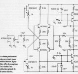
That makes sense, if we are using P and N mosfets (with different Vgs), like the picture below? (adjustable CCS)
The selection of VAS device, if we want to consider its gain, Mosfets and Fets have lower gain than bipolars. But bipolars have much more predictable Vbe (about 0.65V always). Using mosfets must have different value CCS, or different resistor from differential legs.
Can we use bipolars with Re to get about the same gain as mosfet or fet, for VAS device? Will the sound of degenerated bipolar the same as if we use mosfet/fet?
What is the calculation to degenerate gain of bipolar with Re? (To have the gain about the same as if we use mosfet/fet)
Hi, Fred,
I would defiinitely go with the two current sources instead of the self biasing route, due to the different turn on voltages and transconductances of P channel and N channel mosfets that would be used in mosfet voltage gain stage.
That makes sense, if we are using P and N mosfets (with different Vgs), like the picture below? (adjustable CCS)
The selection of VAS device, if we want to consider its gain, Mosfets and Fets have lower gain than bipolars. But bipolars have much more predictable Vbe (about 0.65V always). Using mosfets must have different value CCS, or different resistor from differential legs.
You mean like emiitter followers? Try some emitter degeneration you might be suprised.........
Can we use bipolars with Re to get about the same gain as mosfet or fet, for VAS device? Will the sound of degenerated bipolar the same as if we use mosfet/fet?
What is the calculation to degenerate gain of bipolar with Re? (To have the gain about the same as if we use mosfet/fet)
Attachments
slowhands said:
To quantify these effects, in the early 70s audio engineers labelled the collection of effects TIM and developed new tests to measure it (Dynamic Intermodulation Modulation "DIM"). DIM is measured using a low frequency, higher amplitude square wave mixed with a high frequency sine wave (specifically, 3.18 kHz square wave, 15 kHz sine wave, mixed 4:1, amplifed and spectrum analyzed, distortion products measured in %).
I am looking for reference documentation on DIM measurement. Do you have something to suggest. Or does it say it all in your description? I have never seen any quantified specification on DIM on commercial audio product.
Thanks
Much obliged Jam 😉
By the way, can you send some of them Jfets (the 389s) this way too?
Name your price, you can ask Jocko, I am good for it. Of course that is unless Jocko has them in which case I would buy them from him as I tend to be a loyal customer.
Fred
I can always put an enema to good use. I see your point more than you can imagine 😉
In the 70's (maybe early 80's) Sansui developed an interesting
TIM test, where the amplifier was fed a series of triangle waves
alternating between a sharp rise and slow fall and then a slow
rise and a sharp fall. TIM resulted in a DC shift in the amplifier
forming a square wave with a period corresponding the the
frequency of the alternation of the triangle wave.
Degeneration resistor and distortion
Thanks Mr Pass! Is this method of measuring DC shift similar (even if the waveform used is different) to this one below I found in E & W.W. of 1981? By the way, in this article they have measured the Threshold 4000 and found it good in that manner compared to 3 other models.
But is there a common standard (other than THD and IMD) that is used to compare amps?
Regarding the degeneration resistors isn't it true that too high a value will change the distortion curve in function of power level;instead of having a sharp increase of distortion only close to the clipping level, the distortion would begin to rise at lower power levels but with a lower slope until clipping? If true, could it be caused by the reduction of overall feedback due to lower gain in input stage?
Nelson Pass said:In the 70's (maybe early 80's) Sansui developed an interesting
TIM test, where the amplifier was fed a series of triangle waves
alternating between a sharp rise and slow fall and then a slow
rise and a sharp fall. TIM resulted in a DC shift in the amplifier
forming a square wave with a period corresponding the the
frequency of the alternation of the triangle wave.
Thanks Mr Pass! Is this method of measuring DC shift similar (even if the waveform used is different) to this one below I found in E & W.W. of 1981? By the way, in this article they have measured the Threshold 4000 and found it good in that manner compared to 3 other models.
But is there a common standard (other than THD and IMD) that is used to compare amps?
Regarding the degeneration resistors isn't it true that too high a value will change the distortion curve in function of power level;instead of having a sharp increase of distortion only close to the clipping level, the distortion would begin to rise at lower power levels but with a lower slope until clipping? If true, could it be caused by the reduction of overall feedback due to lower gain in input stage?
Attachments
Have anyone Experimented with Re in differential?
What happens if we place inductor for Re, instead of resistor? Inductor have raising resistance with frequency.
What happens if we place resistor//with capacitor for Re? Like 1k//with capacitor. Capacitor has less resistance with raising frequency.
Or those experiment is dangerous, because to oscilation possibilities?
lumanauw said:Have anyone Experimented with Re in differential?
What happens if we place inductor for Re, instead of resistor? Inductor have raising resistance with frequency.
What happens if we place resistor//with capacitor for Re? Like 1k//with capacitor. Capacitor has less resistance with raising frequency.
Or those experiment is dangerous, because to oscilation possibilities?
Having 1k//with capacitor: it depends of cource of the capacitor value. I have already used that scheme to polarize a j-fet input stage with a very low cut-off frequency so I would have the stable gain I needed for the whole audio range. Here in a BJT differential pair, there is no need for that unless, if I understand your point is to vary the gain of the input stage against frequency. At low frequency (where C is seen as an open circuit) you would have a gain of about only 1.8 in input stage ! This is too low.
The amount of overall feedback of the amp would increase as frequency increases. I would tend to believe that oscillation problems may be hard to solve.
Uli published this circuit in the thread “normal X-Amp”. I’m surprised, it got little attention. I believe it to be very close to the x600 and 1000x. The amp uses one more cascade in the signal path then the x600 and x1000. That is an improvement. The one short full of this amp compared to those smaller X-amps is that it needs a balanced input. It’s not hard for us diyrs to build a balancing preamp for this amp.
Some changes we talked about, that Uli is trying is to remove the 100 ohm magic resistor for even more X effect and removing the 100k ohm resistors on the gates of the Input mosfet. I don’t think you need the RC networks on the outputs of the amp.
If NP or any others know of any other way to get better performance out of the circuit, let me know.
Attachments
- Status
- Not open for further replies.
- Home
- Amplifiers
- Pass Labs
- PassDIY and Leach paper