Reducing the value of the J-fet drain resistors cannot compensate the huge gain if the VAS transistors, not degenerated, only with a load at the FE output I got values of OLG Nelson seems to speak of....
😀😀
I agree with that analysis.
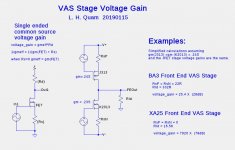
Here are some calculations and a comparison of the BA3-FE degenerated VAS stage with the XA25 undegenerated VAS stage.
Attachments
A diversionary tactic. I am from an era when thermo cycling was said to weakened/disconnect pads and loosened hardware. The XA25 idles at 240 Watts it seems. The temperature swings are impressive if I turn it off. It has been on 99% of the time for the past month. Am I apt to risk a shorter lifespan if I shut it down at night? Would a schematic shed any light on answering this question? For now, the XA25 is earning its keep by being synergistic with my gas heat. But, before long, it will be antagonistic with my cooling system.
Last edited:
I have 40 year old Stasis 1's here that ran harder than that, so I
wouldn't worry about it. Parts are being used at conservative
power and temperature.
Maybe you will like to spend the summer with a nice Class D amp,
staying cool and preparing for the contrast you'll have when the
weather gets cold again...
😛
wouldn't worry about it. Parts are being used at conservative
power and temperature.
Maybe you will like to spend the summer with a nice Class D amp,
staying cool and preparing for the contrast you'll have when the
weather gets cold again...
😛
Now there is a cool idea - how about a Nelson Pass design Class D amp for the Summer months and then any of his traditional all Class A designs for the Winter months.
I am sure Nelson could cook up a good Class D amp, put his name on it and it would sell like hot cakes - or should that be cold cakes, anyway just a thought. Maybe just come up with a design for all the addicted ones around here.
I am sure Nelson could cook up a good Class D amp, put his name on it and it would sell like hot cakes - or should that be cold cakes, anyway just a thought. Maybe just come up with a design for all the addicted ones around here.
Thanks for the information. It seems that the XA25 has a longer life expectancy than me. She appears to be burned in, stable, and wonderful. I shall start shutting her down at night and when I am away.I have 40 year old Stasis 1's here that ran harder than that, so I
wouldn't worry about it. Parts are being used at conservative
power and temperature.
😛
how about a Nelson Pass design Class D amp
Been there, done that. See pic in upper right? That's a Class D Threshold. 🙂
FIRST WATT
Class D! I'd rather put the amp outside and knock a hole through the wall for the cables
Given that it tops 40 deg C in the shade around a few of the places I've lived recently, I'd feel sorry for the amp!
I am not fooled.
This is only intended to provoke me into revealing the actual schematic.
😛
You got it!
🙂
Nevertheless I tried what you wrote with the load change of the J-Fets and when I went down to a ridiculous value of 10R for the drain resistors of the J-Fets the OLG went down to about 45dB. Of course still some R on the output to GRD, but moderate in the range of 15k.
So I will give this degenerated FE a chance and hear.... these experiments are always fun.
You also have the option of using cascode local feedback to reduce the gain of the VAS, which also incidentally increases the FE loading...
Yes, will try all three possibilities .....
- load resistor 1k at the FE output
- smallest J-Fet drain resistors
- cascode feedback, here I remember that Nelson recommended only 10dB by them, this
could be not sufficient, we have to come down from around 70dB to 40-40dB OLG.
But at the moment I enjoy the sound of the FE with the small J-Fet resistors ......🙂🙂
Errrm... NO! 🙂
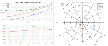
If you are serious about lowering the open-loop gain, and thus also lowering the level of negative feedback, you probably want to adjust the 2nd harmonic (H2) phase. ZD25 (an approximation to the XA25) with its high open-loop gain (more than 60dB) has a 2nd harmonic with positive phase as shown in the plots below. Cascode local feedback is one way to "tweak" the phase of the 2nd harmonic.
These plots show the ZD25 2nd (H2) and 3rd (H3) harmonic amplitudes and phases as a function of frequency at 8 Watts into 8 Ohms. The plot on the right is something you have probably never seen. It is a polar plot where the distance from the origin is a amplitude (in dB) of the H2 and H3 harmonics, and the angle is the phase of the H2 and H3 harmonics.
These plots show the ZD25 2nd (H2) and 3rd (H3) harmonic amplitudes and phases as a function of frequency at 8 Watts into 8 Ohms. The plot on the right is something you have probably never seen. It is a polar plot where the distance from the origin is a amplitude (in dB) of the H2 and H3 harmonics, and the angle is the phase of the H2 and H3 harmonics.
Attachments
Last edited:
Yes, will try all three possibilities .....
- load resistor 1k at the FE output
- smallest J-Fet drain resistors
- cascode feedback, here I remember that Nelson recommended only 10dB by them, this
could be not sufficient, we have to come down from around 70dB to 40-40dB OLG.
But at the moment I enjoy the sound of the FE with the small J-Fet resistors ......🙂🙂
You are enjoying the sound which is the most important thing 🙂
I think you will need all three of the above although in practice it may well be better to increase the value of the input JFET shared source resistor rather than decrease the drain load. The JFETs don't have to work so hard then and consequently produce less distortion.
The funny is that when I tune the FE version with the low drain resistor and the version with a 1k load to the same surrounding conditions, the both show the same distortion.
I checked the wattage for the J-Fets, cascode transistors in both versions in Spice and also funny, hope i made no mistake, they were very similar.
I also expected a hooottter J74/K170 combo.
😀
I wil do the simu again, to be sure ...
I checked the wattage for the J-Fets, cascode transistors in both versions in Spice and also funny, hope i made no mistake, they were very similar.
I also expected a hooottter J74/K170 combo.
😀
I wil do the simu again, to be sure ...
Both a 1K FE load and a 10R drain resistor are fairly tough loads so perhaps it is not so surprising. For lowest distortion you are likely to be better off using higher values and a combination of cascode local feedback, FE load and increased input JFET resistor to ground. Well, that is what I found anyway.
You will be right, Pa did it this way in the Sony.
Nevertheless the distortion was even in real near 90dB.
Nevertheless the distortion was even in real near 90dB.
About a year ago I did similar experiments with my ZD25 build. I built two (stereo) copies of the ZD25, one with the original high open-loop gain (OLG) and the other modified in a variety of ways. If I remember correctly they were:
Disclaimer: Other people might have better ears, and different speakers, listening rooms, and musical tastes.
- different FE load resistors
- cascode local feedback
- different resistor values in the JFET source feedback network
Disclaimer: Other people might have better ears, and different speakers, listening rooms, and musical tastes.
- Home
- Amplifiers
- Pass Labs
- Pass XA25?