Vishay Powertron is suppose to be "colorless", so if one wants superior power resistors, these should be short listed.

yup
especially if you re-purpose parts from some Lab or Measuring....... in general heavy Pro equipment
my fave way

especially if you re-purpose parts from some Lab or Measuring....... in general heavy Pro equipment
my fave way
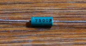
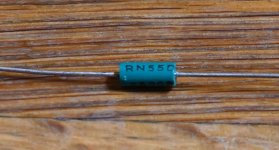
Maybe someone can tell me which brand these resistors are. RN55 "sounds" like a Dale type but does not look like it.
The history of them are that my father was a "collector type" so a room in my parents house was filled with "tons" of old electronic components / equipment. Room needed to be cleaned up so I have trashed many of these. Many plastic bags of components / equipment. I never tought I would go into the "DIY hobby". I found a couple of these that had survived. I guess they maybe are 50 years old or more.......
The history of them are that my father was a "collector type" so a room in my parents house was filled with "tons" of old electronic components / equipment. Room needed to be cleaned up so I have trashed many of these. Many plastic bags of components / equipment. I never tought I would go into the "DIY hobby". I found a couple of these that had survived. I guess they maybe are 50 years old or more.......
Attachments
Ok!
Thank you! TT Electronics......never heard of those.
Obsolete.......metal glazed........it looks like green plastic.
If not trashed I could have build IronPre with those......
Thank you! TT Electronics......never heard of those.
Obsolete.......metal glazed........it looks like green plastic.
If not trashed I could have build IronPre with those......
Pa is using supersymmetric resistors
and, whenever he parallel them, orientation of readout is opposite, that increases supersymmetry
one day, when I grow up, maybe he'll tell why he's using same ones in non-supersymmetric circuits
someone just liked this above and I'm totally surprised how sometimes I'm even more clever than my usual level of Omnicleverness
and - my Omnicleverness would be stratospherically greater, only that I'm capable to remember at least half of what I wrote

Just wait until Panasonic launches the ultrasymmetrical resistors. That rant will be utterly pricelessezz!
I like to have the more clever people designing circuits and PCBs!

A "standard DIY size" could be agreed on for the "small signal" circuits so we all could get a cabinet with full E96 series with 1000 of each value in 1%.
The 01005 series would not take up much space. Then my stereo microscope would see more use........and the small Weller tips I have.......
A "standard DIY size" could be agreed on for the "small signal" circuits so we all could get a cabinet with full E96 series with 1000 of each value in 1%.
The 01005 series would not take up much space. Then my stereo microscope would see more use........and the small Weller tips I have.......
The best resistor is basically Vishay foil and I have an upcoming amplifier build which I am considering using the naked version on the gate and the Powertron on the source and MELF on everything else.
Hello Oneminde,
Vishay foil resistor are expensive and claim high performance. If you look at the data sheet that claimed performance is claimed for DC operation.
The foil resistors are very light in mass and the metal resistive element is exposed to the air. When used for AC applications they heat very rapidly because of the light mass, They also cool very rapidly for the same reasons.
This rapid heating and cooling causes significant changes of resistance with nonlinear distortion as a result. This heating/cooling cycle has more time to to cause distortion at lower audio frequencies. Higher frequencies are not distorted as much.
This foil resistor distortion was discussed by Bruce Hoffer of Audio Precision.
Vishay PTF resistors with Higher mass and with lower PPM numbers test best on my bench. Placing a network of PTF resistors in series and parallel has less heat per resistor and tests even better.
Thanks DT
vishay.com/docs/31019/ptf.pdf
For surface mount
vishay.com/docs/30162/psf.pdf
Last edited:
Coming from electronic ignorance and basically staying there by lack of time and talent, I basically follow the recommendations of the masters, (even though their opinions can differ...) — the component should suit its duty.
Most say to stop worrying and learn to stick to the specs, few say to take care on delicate positions. That's the path to follow IMO. Take it easy, and use what you prefer as long as both the specs and your tastes are served well...
vishay's CMF/RN series, prp, and Amtrans AMRG are easy to use (written values), although the higher rated/bigger CMF are ugly. CMF50 (1/4W) are tiny, the dark blue look is wonderfully geeky 🙂
"Some say" susumu are best for SMD…
There's at least one of the true masters who goes down the rabbit-hole and recommends vishay naked/charcoft Z-foils and other exotic parts (for the really delicate signals)...
Regarding DIY assembly with surface mount resistors (& capacitors):
The resistors will be 1% metal film, unless you want try really hard to source something else.
The capacitors would be ceramic dielectric of type C0G or X7R depending on value. There is some debate about the piezoelectric effect of the dielectric and its audibility. I would feel safe with small values, <1000 pF, in C0G, and values up to 0.1 uF in X7R.
From my days of assembling prototype circuits to test out my design ideas, Imperial size 1206 is fairly straightforward to solder without special tools other than a smaller tip on the soldering iron. Having a circuit board clamp will make things much easier to hold parts in place. Fine point tweezers will also help. Going below 1206, I used to solder 0805, 0603 and even 0402 with the aid of a binocular microscope and special soldering iron. Those tools are not cheap. Fortunately my previous company was footing the bill.
Overall, I would recommend 1206 as a standard size. It works well in compact highly populated layouts. Imperial 1210 or above would only be needed if higher power dissipation were necessary. Something to bear in mind is that the values are printed in a three or four digit code, which one needs to look up in a database (or the manufacturer's data sheet). The SMD codes are nothing like the digit codes that we are already familiar with on Vishay/Dale axial leaded parts. You will need a magnifier of some sort to read the code. Best to keep the different values carefully segregated.
so, if we stay with Pass preferred resistors (size), where we are ?
ZM soldering 0805 in pads of 1206, only when Vendor send those (availability, error) and dissipation/voltage isn't critical
active smd critters - well, if I put it on pcb, I'm going to solder it
now, I'm not going further than first optimizing parts (wattage, voltage), then optimizing pcb for circuit (again - thermal arrangement being very important - how far OS devices are, how far caps are from heat sources), overall pcb dimension is always result of thinking how to wire and in context of overall construction and preferred/necessary case dimension
now, I'm not in mobile phone construction business .......... so no need to think of that level of miniaturization
I am getting product lifecycle change notifications on a regular basis. A lot of the components that we have become accustomed to using in Pass DIY designs will be obsolete soon. One of the biggest factors driving the component obsolescence is the switch to SMD packages.
We should be thinking in terms of SOT23 or SOT223 instead of TO-92 or TO-126. That will be the way forward. Fortunately the SOT23 and 223 are similar to 1206 as far as ease of soldering is concerned.
We should be thinking in terms of SOT23 or SOT223 instead of TO-92 or TO-126. That will be the way forward. Fortunately the SOT23 and 223 are similar to 1206 as far as ease of soldering is concerned.
When I looked at Digikey it looks like there is 0 stock for a lot of the Silmic 2 caps
and most of those it still has in stock are now marked as obsolete.
and most of those it still has in stock are now marked as obsolete.
- Home
- Amplifiers
- Pass Labs
- PASS preferred resistors