Maybe I saw too many US soap opera in TV. They say "I'll sue you" very easily. NP said that Monster Cable sue everyone using word "Monster" (not even copying the product)
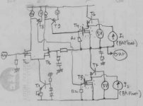
This is what I have in mind. All aspect from this design is from Mr.Pass's tutorial (I think he don't realize it)
First, the goal. I want to make amp, as simple as possible (minimal stages), with input stages that can handle big voltage (Mosfets here), low OL gain with high OL bandwith (passive folded cascode here-from SuSy), with this patent offcourse, sounds good, hopefully with efficiency.
The finals are mosfets (NP said for mosfets suitable for hot operation), cascoded 5V by bipolars, and around each final there is floating 7A current source.
The bias section (which I learn from "Smart Bias" patent) don' use VBE multiplier biasing scheme, but rather bias is determined by T1, and this T1 is put in heatsink for thermal compensation.
The finals are driven exactly the same way, for upper and lower section, both are Nch mosfets.
I know I break many NP's patent in this cct (how many that I break?)
There is still 2 question.
1. For the cascode device (here I draw bipolars) what is the most suitable? Mosfet also, or bipolars?
2. I wanted to exclude the final stage from the feedback loop. In ordinary design with VBE multiplier bias scheme, I can easily do that by taking feedback point from VAS.
But how to do it here?
Attachments
This schematic is nonsens - " low " cascode is wrong. Don't look only at " Pass'es ", look also at Halcro or older Haggard connection. 😉
Hey! My pc and monitor is gobbling up ~150 watts just reading this.Nelson Pass said:Is listening to a 200 watt (idle) amplifier worth 1% of driving your car around?

Upupa Epops said:This schematic is nonsens - " low " cascode is wrong. Don't look only at " Pass'es ", look also at Halcro or older Haggard connection. 😉
Is it wrong? I looked and didn't see an error, although it's
a greatly simplified circuit.
To Nelson : You have right, lower cascode is variable current source. But whatabout unsymetrical clipping ?
From the looks of it, you'll see severe distortion as the Cascodes
collapse, and that should be reasonably symmetrical - within
a couple of volts. I don't expect to see the output approach
the rail better than about 6 or 7 volt loss.
collapse, and that should be reasonably symmetrical - within
a couple of volts. I don't expect to see the output approach
the rail better than about 6 or 7 volt loss.
Nelson, I like Mosfets the same as you like - I know, how works this devices 😎 - solution is easy, little bit higher + rail voltage on VAS 😎 .
Back OT on the heat tip...
I'm planning some wintertime amps--a pair of SOZ-lites built into torchier lamps. I soothe my conscience thusly:
I'll go home this evening and turn on two 300W halogen lamps to light my living room. Those watts will be welcome guests in my home, as it will be many degrees below freezing outside tonight. Every watt in my house that doesn't come from electricity must come from my none-too-efficient NG furnace. And, reviewing my gas bill and the rising price of NG, I notice that the savings to be had there is shrinking.
Ergo my plan for a healthy SOZ with a bank of halogen projector bulbs for resistors--light, heat, and music on a winter's eve. Now that's what I call efficient.
/Bill/ believes entropy happens--but it's the journey that's important, not the destination.
The 7A floating current source is not used variably, but always steady at 7A, at all condition.To Nelson : You have right, lower cascode is variable current source
Yes, the higher voltage at folded cascode/VAS will be usefull. I also forgot to draw gate stopper resistors.
Perhaps OT to the main thread...
Don't forget that typical thermal power station efficiency is about 40%, and by the time it goes through many transformers and miles of wires to get to you, the efficiency is down to about 30% or so. Even a lousy gas furnace can generally get 60% efficiency, really good ones over 90%. So if you only want heat, make it where you want to use it with NG. Or better still, have a co-generation setup where the waste heat from the generator engine warms the house while the electricity makes music.Bill F. said:Every watt in my house that doesn't come from electricity must come from my none-too-efficient NG furnace.
Upupa Epops said:Nelson, I like Mosfets the same as you like - I know, how works this devices 😎 - solution is easy, little bit higher + rail voltage on VAS 😎 .
That's how we do it on X600 and X1000's. Works like glue on
a folded cascode.
😎
Did you end up building something along these lines?lumanauw said:...
The finals are mosfets (NP said for mosfets suitable for hot operation), cascoded 5V by bipolars, and around each final there is floating 7A current source.
The bias section (which I learn from "Smart Bias" patent) don' use VBE multiplier biasing scheme, but rather bias is determined by T1, and this T1 is put in heatsink for thermal compensation.
...

- Status
- Not open for further replies.
- Home
- Amplifiers
- Pass Labs
- Pass Patent 5,343,166