Nice work Stafano!
I was planning to post some photos, but....
Today I opened it again, just to remove the transformer. A friend of mine will make a small wooden box for the transformer, then this small box will go back ito a big one...
Seems weird, but the thing is that this is the only way to get rid of the transformer buzz (hum) that was really annoying. Will see (hear) in the next few days...
Regards,
Vix
Upsss...sorry for a typo.
I misprinted your name. Stefano.
By the way, maybe you can take some pics of the interior. (or, is it too messy😀 )
Vix
I misprinted your name. Stefano.
By the way, maybe you can take some pics of the interior. (or, is it too messy😀 )
Vix
Cascoded Zen confused me
Hi!
I would like to build the ZenV8, but here in Europe-Hungary I cann't buy the Lovoltech Jfets. So, I was planing to build the circuit with only Mosfet instead of the Jfet, because I read in the Zen V8 article that it could work but with higher distortion: "...Compared with a comparable MOSFET in the same circuit, it show about 1/3 the distortion...."
But now I am a bit confused:
I asked Mr. Pass about to use Mosfets instead of Jfet in the circuit, but his answer was not totaly clear to me. He wrote:
"Absolutely.Just Cascode a Zen . My original design for the F3 was precisely that, but did not use feedback."
Grey answered to Vix's similar question:
" I'm afraid that you can't use the Zen #8 schematic as-is with a MOSFET on the bottom. The LU1014D is a depletion device, which means that its Source needs to be more positive than its Gate. The IRF MOSFETs are just the opposite--their Gates need to be more positive than their Sources."
1, Am I understand well, that the original ZenV8 circuit is not working with this simple change like to use Mosfet instead of Jfet??
2, How could I build a Zen without Feedback? (it is an old
question)
3, Is it possible to cascode even the ZenLite and use without feedback?
For Vix: I attached the schematic with your modifications. Is it what you mean or I missed out something?
Greets:
Tyimo
Attachments
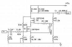
Exactly. C2 should be 1000 uF (Seems to me that you wrote 100 uF on the schematic). Input cap is 3,3 uF just because I happened to have that value. You can experiment with other values to see which works best for you.
Try this version, it will work.
Try this version, it will work.
Tyimo,
You can also add one 100 ohm (or 220 ohm) resistor directly at the gate of Q1 (as in other Zen variations).
Vix
You can also add one 100 ohm (or 220 ohm) resistor directly at the gate of Q1 (as in other Zen variations).
Vix
Tyimo,
First off, you should contact David Briggs (dhole here on DIY) about getting some Lovoltech JFETs. I'll be shipping out some parts to him today or tomorrow. He has agreed to handle Europe
Second, this bias thing is going to drive some of you guys crazy. I feel your pain, as the expression goes. Only for me, it worked the other way. I came to solid state from tubes and had a really hard time dealing with the idea that you had to push the base of an NPN transistor positive to make the stupid thing work. What do you mean positive? Pushing the grid in a tube positive is Really, Really Bad. And here people were telling me I had to do it as a matter of routine in solid state...well, no wonder solid state sounds so bad compared to tubes! I mean, jeez, guys...everyone knows not to push the grid positive!
Well, time passed and I got semi-used to the idea of pushing the control element the "wrong" way, but now the tables are turning and I get my revenge.
(Insert proper mad scientist cackling with glee sounds here. It wouldn't hurt to visualize me grubbing my hands together.)
Now I get to watch while you fellas come to terms with a part that's depletion mode.
Alain Dupont posted a schematic for a cascoded Zen in one of these threads, but I can't remember which one. There were a few details that needed attenting to, but I can't remember whether he posted an amended schematic or not.
Your schematic looks okay, bias-wise, but you might want to consider using a pot to drive C2, assuming that you're using it to do Nelson's modulated cascode thing. Running it wide open like that isn't necessarily going to be the best setting.
I'm not sure why, but a lot of people are posting schematics with just the cap and not the pot. Did I miss a post somewhere where that was suggested?
Grey
Tyimo,
I was confused as well.
Grey,
I replaced the 20K pot with a fixed 47K resistor (and then used P1=10K to set the bias). I know that this may not be the best setting, but it works. (At least until I get some Jfets)
Thanks a lot for your input.
Regards,
Vix
I was confused as well.
Grey,
I replaced the 20K pot with a fixed 47K resistor (and then used P1=10K to set the bias). I know that this may not be the best setting, but it works. (At least until I get some Jfets)
Thanks a lot for your input.
Regards,
Vix
Hi!
Grey, thanks for the infos!
I think you wrote in post 290 : " ...Assuming that Q1 is a MOSFET, then you don't really need to adjust the Gate of Q2 at all. Use a fixed voltage divider to set Q2's Gate some workable distance above ground...say, 10 to 15V as a minimum..."
But it is possible that I didn't understand you.
Vix: here is the corrected schem. Do you mean this?
Greets: Tyimo
P.S.: My main questions are not answeres yet. :-(
How is it possible to build a Cascoded Zen without feedback?!?
Grey, thanks for the infos!
I'm not sure why, but a lot of people are posting schematics with just the cap and not the pot. Did I miss a post somewhere where that was suggested?
I think you wrote in post 290 : " ...Assuming that Q1 is a MOSFET, then you don't really need to adjust the Gate of Q2 at all. Use a fixed voltage divider to set Q2's Gate some workable distance above ground...say, 10 to 15V as a minimum..."
But it is possible that I didn't understand you.
Vix: here is the corrected schem. Do you mean this?
Greets: Tyimo
P.S.: My main questions are not answeres yet. :-(
How is it possible to build a Cascoded Zen without feedback?!?
Attachments
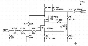
I was speaking of setting the operating point for the cascode device, not the cascode modulation--that pot should stay. Sorry if anyone got confused.
Okay, regarding bias...here's the deal...you've got yourself an LU1014D. It's a depletion mode device. What that means is that the Source needs to be more positive than the Gate. I know this isn't what you're used to, but it's the way things have to be. There are several ways to accomplish this, but the easiest is to use a resistor under the Source and tie the Gate to ground. That way the current drawn through the device will go through the resistor. The resistor will then show a voltage, which will in turn lift the Source above ground.
Congratulations, you have just biased the device.
And you thought that the resistor under the tail of that JFET was like the ones under the emitters of the big bipolars you're used to--the ones you use to balance current or apply local degenerative feedback. Well, yes, that too...but in a depletion mode device it helps set the bias.
This will hang a lot of people up, so I'm going to say it again: The resistor under the Source of the device sets the bias. It's that simple.
Is there more to it than that? Naturally. The voltage applied to the device is also involved. The more voltage at the Drain, the more electrons will be tempted to cross through the device. This means that you can use the voltage at the Drain to set the bias. This is the method that Nelson chose to use in Zen #8.
Note that either of these methods work pretty well with a single rail.
There are other ways to manage the bias, but they require more parts. So far, we've gotten away with the addition of a single part--a resistor--which is about as low-impact as you can hope to get.
If you've got a chance to put in a negative rail, it opens other biasing options, but that will have to wait for another post.
Grey
Thanks Grey!
It is very interesting what you wrote about the Mosfet's "mentality. 🙂 I didn't know this bias methode and I always learn a lot from you comments!
But, should I ask You and others again:
How could I build a Cascoded -MosFet- Zen without feedback????
For example, if I would use Vix's schematic?
Greets:
Tyimo
Multiple JFETs
To use multiple JFETs I presume one needs to match the JFETs and use only one MOSFET for cascoding, correct?
OR
One could use multiple pairs of JFET/MOSFET Cascodes, so that each JFET will be individually manipulated by the MOSFET for the required optimal operation, correct?
I wounder if the JFET/MOSFET combo will track each other across the operating range?
I presume in both the above cases one would use one source resistor.
SMathews
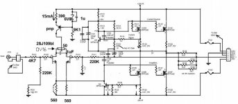
GRollins said:It would not surprise me if it turned out that the single transistor nearest the dual JFET was a CCS connected to the Sources of the JFETs in order to make it a better differential.
If we are to assume that the JFET is, in fact, a 2SJ109, then it would be entirely appropriate for the CCS to be something like, say, a ZTX550. Just for giggles, you could shoot for something like 5-10mA through the CCS, depending on whether the 2SJ109 is GR, BL, or VI.
That should be enough to get you started.
Grey
grey-what you think about possibility that Nelson use two 2SJ109V-s in parallel?

and another Q :
any idea for few single Jfets in parallel,to replace sj109 and to achieve at least 20mA through,without mocking dissipation
in the end,I'll just put tube LTP in front,)

Tyimo,
Since you insist on a non-fedback variant, the only way I can think of is to bias Q1 in different manner (so you won't have a feedback loop), maybe something like in a Bride of ZEN. You may also need to increase the value of the source resistor, to 1 ohm or so.
Regards,
Vix
Since you insist on a non-fedback variant, the only way I can think of is to bias Q1 in different manner (so you won't have a feedback loop), maybe something like in a Bride of ZEN. You may also need to increase the value of the source resistor, to 1 ohm or so.
Regards,
Vix
Grey wrote:
"There are several ways to accomplish this, but the easiest is to use a resistor under the Source and tie the Gate to ground. That way the current drawn through the device will go through the resistor. The resistor will then show a voltage, which will in turn lift the Source above ground."
Hey Grey, looking over the JFET amp's topology, might this afford the opportunity to connect the AC load (speaker "-") directly to the Source (instead of ground) ala Ultrapath and parafeed circuits used in tubeland?
Coming from a tube world I just couldn't see not shortening that long AC current path. With an active CCS, the metered DC biases up the cascode nicely, but appears to be less than ideal with AC. Wouldn't this AC current be better summed at the JFET's Source, well isolated from the PS?
It would stabilize the Source voltage, remove degeneration, and should provide more direct loading of the JFET. Triming distortion via modulating the cascode might yield finer results.
Combining all AC loads at the Source (not ground) provides a shorter AC loop and a common AC point reference (think: star ground -with the CCS metering out current and the Source resistor sinking it).
I dunno.... just throwing out more fodder.
Steve
PS Thanks for the power JFETs, Grey.
Tyimo said:
How could I build a Cascoded -MosFet- Zen without feedback????
Tyimo
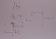
Cascoding the Son of Zen works fine . It is probably the unique circuit for mosfets working by not using the DC feedback loop.
Vix said:
maybe something like in a Bride of ZEN.
I tried it , and believe it doesn't works good ... at least with a ccs load .
Tyimo,
Honestly, I've kinda gotten lost as to whose version of which schematic is under discussion. I'd offer to whip one up, but I'm a little snowed under with the JFET buy, the JFET circuit I'm pulling together, and a desperate attempt to get some writing things taken care of before my editor comes after me with a pitchfork.
SMathews,
I'd recommend one MOSFET per JFET. If nothing else, you're not going to want to ask that much of the MOSFET in terms of power dissipation. There are other reasons, but that's enough to be getting on with.
choky,
I think it's unlikely that Nelson is paralleling '109s. That's not to say that you can't do it if it suits your needs.
Vix, et. al.,
I know it's heresy, but might I humbly suggest the use of a negative rail? Then you can tie the Gate to ground and simplify just about everything.
steve jones,
Don't forget that in tubes, the transformer constitutes a load, not only in and of itself, but in terms of reflected impedance.
Taking the signal from the Source can be done...as will be seen (hopefully) shortly.
stefanobilliani,
You can get a CCS to work as a load, it just takes a little fiddle factor.
Grey
GRollins said:
choky,
I think it's unlikely that Nelson is paralleling '109s. That's not to say that you can't do it if it suits your needs.
Grey
yup;
that was just a glance of idea......
so I resume that Nelson didn't use more than 20mA in LTP;or even less,taking 200mW dissipation in account,and presuming around 20V D-S........
for greenhorn like me,that looks like at smallish side,but can I argue with a man who make amps with 3+ zeros price tag..........?


- Status
- Not open for further replies.
- Home
- Amplifiers
- Pass Labs
- Pass JFET Power Amplifier