Moving some air past it will help a lot. For 100 watts, I would think you need more than one heatsink. Parallelling transistors and putting them on different sinks should more than double the transfer efficiency. Of course, that's bigger yet...
I thought about putting two back to back (one with a channel for mounting the devices). This could help.
I also spent some more time on the Thermaflo site. It seems I do not understand thermal resistance because it seemed like some of the sinks with values of around 2 were much better - close to what would be needed.
Don't know what to make of that.
Paul
I also spent some more time on the Thermaflo site. It seems I do not understand thermal resistance because it seemed like some of the sinks with values of around 2 were much better - close to what would be needed.
Don't know what to make of that.
Paul
Hi there!
This weekend I have completed the Zen V8, however with a mosfet instead of jfet. Q1 is IRFZ44N while Q2 is IRFP250N. The circuit looks like "cascoded zen" (original one). Q1 is biased as the original zen, with P1 of 10K0hm from the gate to ground, and 22 kOhm from the gate of Q1 to the drain of Q2 . (This also serves as a feedback-there is one 2,2 Kohm resistor at the input {4,7 Kohm in the original zen}). There is also an 3,3 uF input cap.
The rest of circuit is as in Zen V8.
P2 (from the gate of Q2 to ground) is 30 Kohm (20k pot +10 k resistor) , while from the gate to drain of Q2 there is a 47 K fixed resistor (like in zen v8). Power supply is unregulated, 48 V (CLCRC).
Current source: One 1500w 220v halogen stick in paralell with 75 Ohm resistor. Measured current: 1.72 A.
So, what I got:
P2 is set at max value. P1 is adjusted so I got around 17 V at the drain of Q2. At the gate of Q1 I measure around 4.9 V.
It seems to work fine....
If there is any idea how to make this better, (not CCS or regulation), please let me know.
Thank you very much for the support,
Vix
Do you have a source resistor on Q1? I think that is a good thing to use. The Zen V8 uses a 0,5 ohm resistor to bias the power JFet but that resistor gives the device som local current feedback as well, making the JFet a lot more linear before global feedback is applied.
Johannes.
Johannes.
Hi,
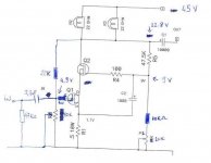
I have done some more testing today. I am attaching a schematic. It is a modified Zen V8, as you can see😀
After adding some resistancle in power supply (it was humming a bit) I have 45 V DC unregulated. Current source: 1500w 220v lightbulb in parallel with 75 ohm resistor.
I am using a 0.5 reistor on the source of Q1. (like on a a schematic).
What I fing difficult and confusing here is setting a proper bias for Q1 and Q2. (Irfz44n and irfp250n, respectively)
I find that I needed to turn P2 (20K) at maximum resistance. With 10 K resistor in series , it has around 30K ohm. Then, with P1 (10 K), I set the voltage at the gate of Q2 to 9 volts. In this case, I got 22.8 v on the Drain of Q2 (around half the supply voltage) and 4.8-4.9 V on the gate of Q1.
Is this setting correct? Or, what shold I do?
Nelson, having in mind that you have already fiddled with "Mosfet-Zv8", your help will be very much appreciated here. I promise to do my homework, and, if sucessful, a final result may be sent to passdiy gallery in a couple of days😀
Thank you very much,
Viktor
Attachments
Vix said:Is this setting correct? Or, what shold I do?
You can always decrease R5 a bit, or you can use a higher value
P2 or resistor in series with the P2. There is nothing magic about
these values as long as you get the DC output where you want
it and keep the Vds of the JFET between about 2 to 3 volts.
😎
Vix,
Assuming that Q1 is a MOSFET, then you don't really need to adjust the Gate of Q2 at all. Use a fixed voltage divider to set Q2's Gate some workable distance above ground...say, 10 to 15V as a minimum.
Your bias for Q1 looks like it will work.
Grey
Assuming that Q1 is a MOSFET, then you don't really need to adjust the Gate of Q2 at all. Use a fixed voltage divider to set Q2's Gate some workable distance above ground...say, 10 to 15V as a minimum.
Your bias for Q1 looks like it will work.
Grey
Thanks!
I will add some resistance in series with P2 (10 K more). (this is easiest for me)
Concering correct voltages, what would be the preferred voltage at the Drain of Q2?
As is, I measured bias current. 1.48 A.
There is also one resistor just after the input cap, 2,2k. (instead of 4.7 K in the original Zen). I may play with it to achieve the desired amount of feedback....
Thank you very much...without your help I wouldn't be able to enjoy this...
Best regards,
Vix
One more thing is a bit unclear. Why is the amount of bias current changing when I change the voltage at the Drain of Q2 ?
(via P1 at the gate of Q1). At first, when I had 17 v at the Drain of Q2, there was 1.72 A of current flowing. Then, when I adjusted P1 so I got 22.8v at the Drain of Q2, but bias current dropped to 1.48 A (bulbs were getting dimmer as well). Power supply voltage was 45 V.
Maybe that's why a Constant Current Source with the Mosfet is better than a resistor/lightbulb?
regards,
Vix
Vix said:One more thing is a bit unclear. Why is the amount of bias current changing when I change the voltage at the Drain of Q2 ?
(via P1 at the gate of Q1). At first, when I had 17 v at the Drain of Q2, there was 1.72 A of current flowing. Then, when I adjusted P1 so I got 22.8v at the Drain of Q2, but bias current dropped to 1.48 A (bulbs were getting dimmer as well). Power supply voltage was 45 V.
Maybe that's why a Constant Current Source with the Mosfet is better than a resistor/lightbulb?
The current through the bulb is proportional to the voltage
across the bulb, which is Rail minus Drain voltage.
It's a given than you can get more efficiency and better specs
with a current source, but not a given that it will sound better.
In ZV8 with a totally new gain device, I wanted to emphasize
the device itself, and so I made the rest of the circuit as simple
as possible. This serves to focus attention on the character
and use of the power JFET, and also encourages newbies to
try the circuit, since a light bulb is less intimidating than a
current source.
Needless to say, there are follow-ups on ZV8 which introduce
current sources and other elements to spice up the performance.
You need only look at the .1% THD of ZV8 at 1 watt and
anticipate the .003% that is possible on more sophisticated versions.
😎
What about replacing existing gain devices in the aleph or ax by the jfet cascode.
I have not studied this thoroughly but it seems that those who want to adapt their alephs to jfet operation would be very interested.
What are the main guidelines for this?
Grey?
I have not studied this thoroughly but it seems that those who want to adapt their alephs to jfet operation would be very interested.
What are the main guidelines for this?
Grey?
As I said somewhere, I think in the Aleph-X Builder thread, it can be done, but I'm not currently interested in pursuing it. Just seems kinda, I dunno...it's just not calling to me.
I will note in passing that there is a certain patent by a certain person that could be deemed relevant to this experiment. No, not the Aleph patent...another one. However, given Nelson's current IP troubles, I'm going to leave it at that.
Grey
I will note in passing that there is a certain patent by a certain person that could be deemed relevant to this experiment. No, not the Aleph patent...another one. However, given Nelson's current IP troubles, I'm going to leave it at that.
Grey
GRollins said:..it's just not calling to me.
I will note in passing that there is a certain patent by a certain person that could be deemed relevant to this experiment. No, not the Aleph patent...another one. However, given Nelson's current IP troubles, I'm going to leave it at that.
Grey
That is a shame!
But I don´t understand the patent problem.Nelson has always been very flexible about diyers experimenting with his designs.Are you saying that if we modded the ax with jfets then we would be copying an existing Pass Labs amp?
I cant wait to see the Penultimate Jfet ZV12 (or thereabout) with printed circuitboard and the whole enchilada😉Needless to say, there are follow-ups on ZV8 which introduce
That will be the day, for us DIY'ers😎
Steen🙂
steenoe said:I cant wait to see the Penultimate Jfet ZV12 (or thereabout) with printed circuitboard and the whole enchilada😉
That will be the day, for us DIY'ers😎
Steen🙂
nope-then you'll wait for ZV18 or something

I dont think so😀 If you love your kids (us😉 ) you dont keep them waiting for too long🙂nope-then you'll wait for ZV18 or something
Steen😎
There are plenty of topologies to explore. We need not flog Nelson's patents to death to make a tolerably decent circuit. The Aleph-X began as a thought experiment for me. It gathered a certain amount of momentum, of course, and a lot of people got interested. That's great. But I'm ready to move on. If you spend forever on one circuit idea you go stale and things get boring.
Life is too short to spend it being bored, don't you think?
Grey
Life is too short to spend it being bored, don't you think?
Grey
- Status
- Not open for further replies.
- Home
- Amplifiers
- Pass Labs
- Pass JFET Power Amplifier