babbelfish Aleph J working


it works
it sings
I'm thrilled!
same sound as with my good tube critters-full,heavy,seducing,delicate,fast,never too loud...............
and all that with mono test Ikebana-like prototype......
PSU is 300VA donut, connected via variac (too much voltage),so VA rating is also downscaled to ,say,200VA ;
25A block Graetz
smooooothing with simple C filter-just two 30.000UF
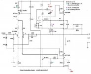
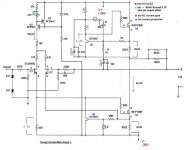
parts-what I have in drawer- exactly as on attached schmtc-mix of MF and carbon resistors,used elcos of 220UF,little bjts what I have on hand.....
I set Iq to 2A
also,I set DC offset after some cooking (test heatsink is just 0,4C/W,with some 8cm PC vent)
I didn't checked AC gain,for now.
I made just rudimentar CRO testing,without looking at clipping behavior;most important what I look is-no signs of oscillation
I'll made extensive tests (capacitive load stability,ringing ,all that usuall stuff) when I make finall gadget- with pcbs,case ,finall heatsinks etc
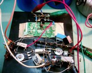
pics of test rig tomorrow,I didn't have my crummy digicam with me this evening
like you can see from schematic-I implemented multiturn pots for LTP CCS (offset and LTP Iq) and same for overall Iq;
it works
it sings
I'm thrilled!
same sound as with my good tube critters-full,heavy,seducing,delicate,fast,never too loud...............
and all that with mono test Ikebana-like prototype......
PSU is 300VA donut, connected via variac (too much voltage),so VA rating is also downscaled to ,say,200VA ;
25A block Graetz
smooooothing with simple C filter-just two 30.000UF
parts-what I have in drawer- exactly as on attached schmtc-mix of MF and carbon resistors,used elcos of 220UF,little bjts what I have on hand.....
I set Iq to 2A
also,I set DC offset after some cooking (test heatsink is just 0,4C/W,with some 8cm PC vent)
I didn't checked AC gain,for now.
I made just rudimentar CRO testing,without looking at clipping behavior;most important what I look is-no signs of oscillation
I'll made extensive tests (capacitive load stability,ringing ,all that usuall stuff) when I make finall gadget- with pcbs,case ,finall heatsinks etc
pics of test rig tomorrow,I didn't have my crummy digicam with me this evening
like you can see from schematic-I implemented multiturn pots for LTP CCS (offset and LTP Iq) and same for overall Iq;
Attachments
one major thing I forget to say:
tnk ya Papa Nelson!
tis days I was contemplating in first time seriously about Aleph series;
I'm just bloody shocked with pure cunningness beside these gadgets....
simple,easy ....
like (seems our mutual appreciabled)writer sez:
"beauty of inner form"
I'm not just stunned with sounding performance ;
I'm stunned with one of the finest examples of fine ,clever and ABOVE ELSE- bloody practical engineering,no matter who was the engineer
cheers again!
Congratulation, Choky !!!!!!
I see you reduced ac current gain somewhat . . .
Around 30%, isn't it . . . ?
Tube boy finally owns a jade . . . 😀
Enjoy !!!!!!
Regards
jh
I see you reduced ac current gain somewhat . . .
Around 30%, isn't it . . . ?
Tube boy finally owns a jade . . . 😀
Enjoy !!!!!!
Regards
jh
jh6you said:Congratulation, Choky !!!!!!
I see you reduced ac current gain somewhat . . .
Around 30%, isn't it . . . ?
Tube boy finally owns a jade . . . 😀
Enjoy !!!!!!
Regards
jh
yur engrish is ulmost bed us mine

reread my post :
I didn't checked AC gain,for now.
btw-yinyang boy
"Tube boy owns another jade" is more adequate...
gundj gundj
where are you with Krazy?
The Krazy?
In a beauty shop for make-up . . .
In a hurry to soon meet her husband, F1 . . . 😀
Regards
jh
In a beauty shop for make-up . . .
In a hurry to soon meet her husband, F1 . . . 😀
Regards
jh
Hi Choky, Congrats on the fine result.it works
I am glad to find you so happy about it😎 Welcome to the club and build yourself the other channel.
Steen.😎
steenoe said:Hi Choky, Congrats on the fine result.
I am glad to find you so happy about it😎 Welcome to the club and build yourself the other channel.
Steen.😎
gundj gundj


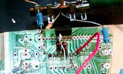
That is splendid work, Choky🙂 I like the way you used an old piece of pcb for connecting that critter🙂 I couldnt see it at first, and it was ofcourse the first thing to look for😀
Steen🙂
Choky you are a... 
Steen🙂
Choky you are a...
Nice circuit.
Isn't the 2sj109 getting a little hot at 200mW+ total dissipation?
The IRFP150N shure will get their feet warm at 50W+ dissipation?
Looking at the size of the sink, your fan should not stop working.
At 250mW+ the lower bc556c in the frontend currentsource is also
living in the tropics, no?
I wonder what your output offset voltage is. I think it could easily
be a volt or so. Don't your speakers care?
Said it before: Nice circuit but you shure like to live a little
dangerous.
Keep up the good work.
Regards.
rtirion said:Nice circuit.
Isn't the 2sj109 getting a little hot at 200mW+ total dissipation?
The IRFP150N shure will get their feet warm at 50W+ dissipation?
Looking at the size of the sink, your fan should not stop working.
At 250mW+ the lower bc556c in the frontend currentsource is also
living in the tropics, no?
I wonder what your output offset voltage is. I think it could easily
be a volt or so. Don't your speakers care?
Said it before: Nice circuit but you shure like to live a little
dangerous.
Keep up the good work.
Regards.
that setup on pics is just breadboard-to verify schematic
in finall iteration certainly will be some polishing;
fan is here as must-just because I have that sink with holes for 4 TO3 cases-plenty holes for needed hardware
all bigger 'sinks I have have no holes drilled,and I'm not in the mood to drill'em without plan 😉
50W per IRFP150N looks dangerous, but it's nothing compared with use and abuse of similar mosfets in PA amps,used in today's trance-dance clubs.....
if I understood correctly-each half of 109 have max dissipation of 200mW ;here I have 2x5mA ,in one leg about 21V and in other about 24,5V ; accordingly-105mW and 122mW. I care more for voltage breakdown- 30V is max for 109 ; hey-if Papa Nelson can do that,why not....
especially -I can't see any other way (except less current than 5mA through each half,but that's dangerously low!) to implement Jfet there.....even if I know that I'm so ignorant in SS field...
regarding CCS for LTP -BC556C is 80V/100mA/500mW/150MHz device ; 250mW in stage looks good enough for me 😉 even if I can change it to some ancient BD140
anyway-important moment for that CCS - both bjts must be placed face to face,thermally coupled-because their thermal contributions are opposite ;when they are coupled (and in that sort of CCS this is must ) everything is pretty stabilized;
base of "inner" BC is referenced to -25V, at least for me -it looks that CMRR is somewhat better in that way
DC offset is stable over time,meaning that probably in each Aclass amp finall setting must be made after full warm-up
in this case- even if BCs are not thermally coupled and I'm well aware that even fan blow over them have influence on DC offset,I have DC offset all the time in range of 200mV overall (plus100 and minus 100).
on finall PCB and positioning in particular case I think that everything will be OK
besides - I saw not just one commercial amp with worse behavior in that area 😉
just to mention-I tried Babbelfish J also as Mini A Babbelfish J - with 0,47 WW ,2x15V ,Iq 1A, and little correction of adequate resistor in current source....... hehe
>Baldrick mode on<
I have a cunning plan:
I already see what I'll do with some spare 120.000UF/15V caps and one nice 250VA donut.........
just to lay my dirty hands on anther pair of 2SJ109.....
>Baldrick mode off<
>50W per IRFP150N looks dangerous, but it's nothing compared
>with use and abuse of similar mosfets in PA amps,used in
>today's trance-dance clubs.....
I beg to differ...
50W+ per device all the time is not common in PA.
PA Amps: Loads of fans, Current limiting circuits, Pre compressors
and what not. Class B and AB at best. Soggy PS's etc, etc.
Not completly the same thing as device usage in a class A amp.
Don't understand this the wrong way. Devices can be driven hard
in any kind of circuit.
50W+ works OK, but you will see a failed device now and then.
That in itself is not a real problem, but the resulting rail voltage
appearance on an output is not liked by zillion dollar, one of a
kind, cost is no object speakers. 🙂
btw Maybe Nelson had an other trick up his sleeve in the J.
Again neat circuit.
Regards
rtirion said:>50W per IRFP150N looks dangerous, but it's nothing compared
>with use and abuse of similar mosfets in PA amps,used in
>today's trance-dance clubs.....
I beg to differ...
50W+ per device all the time is not common in PA.
PA Amps: Loads of fans, Current limiting circuits, Pre compressors
and what not. Class B and AB at best. Soggy PS's etc, etc.
Not completly the same thing as device usage in a class A amp.
Don't understand this the wrong way. Devices can be driven hard
in any kind of circuit.
50W+ works OK, but you will see a failed device now and then.
That in itself is not a real problem, but the resulting rail voltage
appearance on an output is not liked by zillion dollar, one of a
kind, cost is no object speakers. 🙂
btw Maybe Nelson had an other trick up his sleeve in the J.
Again neat circuit.
Regards
regarding PA amps-we both are in right 😉
just think about Peavey or,even better ,HH- in full blast-full clipping almost 95% of the time,all night long,amplifying squares mixed from 50 to 400Hz ... I must mention also several locally made (small production) strictly IRF output amps ; they are really used there as switching elements,but pretty rarely switched off 😀
I agree-50W looks at dangerous side ; I'll try 2 pairs ,as in Papa's Aleph J ,certainly-but in this moment I have just 6 pieces ,not enough to manage two matched pairs;I already decided that I'll made pcbs with off board connection to output mosfets (dedicated pcbs for parallel outputs) ; WWounds can be stacked vertically 😉
DC on output will certainly be disastrous for me,at least with my ancient SS or Iskra or Philips+Goodmans spks
I love my spks more than my amps
that's why I have standalone DC protection- as a part of speaker set,not usually as part of amp 😉
tnx for concern and tips 🙂
PS If nobody else,Nelson will always have some Joker in his sleeve , for sure....
choky said:
. . . can't do ugly like this
😀 😀 😀
Hi . . . Big brother . . .
Regards
jh
regarding rtirion's advices:
I implement one resistor under CCS (Q2& Q3) ,to little ease life for Q2;
another solution was to place something like 2 pieces of BD140-16 back-to-back,but this looks more elegant solution, and little BCs just have more beta .....
thinking about dissipation in output mosfets....
look at SEWA around, ZENs (almost all of them are pretty brutal in dissipation per device) ,older Alephs -especially stronger ones....just in range of 40-45W per device
don't forget that these Alephs are commercial devices...and I resume that Papa Nelson made this decision with some thinkering and experience.......
one important thing - what kill devices (even tubes hehe) is more often temperature,not current (even if temperature is induced with current flow )..
if you can keep that chip cool enough,why not use potential they have ?
ever heard a story about old school radio Hams -cooking 6L6 in bucket of oil,with quadruple max dissipation?...
now I'm thinking about nice Oaken box for Babbelfish J,with two vertical slim and tall heatsinks on front;
front side of each heatsink will be covered with Plexiglass,and each heatsink will have one 8cm PC fan bellow;
top plate will be Oak too,placed on 4 studs in corners,with some 15mm clearance to sides...
oh man-I found today two 2SK332........
now another puzzle -what to do with them.....
....
Attachments
- Status
- Not open for further replies.
- Home
- Amplifiers
- Pass Labs
- Pass JFET Power Amplifier