With reference to the diagram in Post #77, I would suggest using a pair of RSP-200 units, either 24V or 27V, along with the four small filter boards.
Then each F5 channel board would need to have from 20,000 uF to 30,000 uF of capacitance on each rail located close to the PCB.
The combination of 200W SMPS plus energy storage will hopefully do the trick.
Then if that fails, linear supplies with 300W toroids for each channel. 😉
Then each F5 channel board would need to have from 20,000 uF to 30,000 uF of capacitance on each rail located close to the PCB.
The combination of 200W SMPS plus energy storage will hopefully do the trick.
Then if that fails, linear supplies with 300W toroids for each channel. 😉

It depends on the PSRR of the amplifier.\broken record on
why so much additional capacitance?
\broken record off
If the PSSR isn't so good, more capacitance or a cap-multiplier is needed.
If the PSRR is good, much higher ripple is tolerated.
With the F5m topology, the PSRR is good and I measure less than 100 uVrms at the outputs without extra capacitors.
So in the general case an RC filter (big C little r), but in this specific case not needed.
Thx
👍
Thx
👍
Hi Nelson this revision is voiced like big AcaMini ? love soo much is soundShipping in a few days. Two kits, essentials and completion.
Hi
I have built two versions of the amplifier, one with the IRFP240/9240 and another one with the FQA19N20/12P20, both without the thermistors. I liked very much the sound but I noticed that small changes in room temperature resulted in changes in the bias current. I have followed closely from the beginning this interesting thread. So, I am wandering if the 140/9140s are less influenced by the ambient temperature. I also wanted to ask about the time needed for the output transistors to be stabilised to the adjusted bias.
Thanks
It takes a little bit of processing at the "store" before it is listed, but it should be before the end of the month. The completion kit should follow very shortly.

ACA looks to be dissipating ~20W. In the BA'23 video, NP has it running at 48W dissipation and the OP in this thread @65W. Are we really sure we want to drop these "little" F5m boards into an ACA chassis? This is still intended to be a 25W per channel Class A amplifier, far as I can tell. ACA is like... 8W per channel?
F5m article drops this week, and there is an analysis on dissipation numbers for several store sinks.
Any idea when these are going to be in the store?
Scott
Thank you Lynn for opening this thread even before Pa is doing the article!
:--))
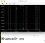
I did the circuit today in Spice and....
I am so astonished how good the simple change from IRFP240/9240 to IRFP140/9140 is changing the THD pattern.
I has the charm of tube rolling! And it shows how good Nelson knows his candidates to use them in their best way!
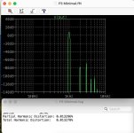
Here the minimalistic circuit THD pattern in Spice with IRFP240/9240 first and second with IRFP140/9140.
Even the distortion values at 1W/8Ohm are lower, though H2 is higher than H3.
Minimalism, I am waiting Nelson does an amp with a half resistor and a half transistor!
:--))
:--))
I did the circuit today in Spice and....
I am so astonished how good the simple change from IRFP240/9240 to IRFP140/9140 is changing the THD pattern.
I has the charm of tube rolling! And it shows how good Nelson knows his candidates to use them in their best way!
Here the minimalistic circuit THD pattern in Spice with IRFP240/9240 first and second with IRFP140/9140.
Even the distortion values at 1W/8Ohm are lower, though H2 is higher than H3.
Minimalism, I am waiting Nelson does an amp with a half resistor and a half transistor!
:--))
Attachments
Last edited:
me too!
and then I'm going to Babelfish it, having 101.5 resistor and 101.5 transistor

and then I'm going to Babelfish it, having 101.5 resistor and 101.5 transistor
It might be easy with a full transistor and resistor shared between two channels....
Minimalism, I am waiting Nelson does an amp with a half resistor and a half transistor!
:--))
- Home
- Amplifiers
- Pass Labs
- Pass F5m