

I've been made aware that listings in the store for the F5M essentials and completion kit were inadvertently made visible before they were complete. They have now been hidden.
The F5M essential and completion kits will be available for sale in the store at 12PM PST / 3PM EST Monday 4th March (see this time in your city).
Thanks for your patience 🙂
The F5M essential and completion kits will be available for sale in the store at 12PM PST / 3PM EST Monday 4th March (see this time in your city).
Thanks for your patience 🙂
It's great to see a definitive time for the F5m kits being available in the store.
I have already progressed far enough with the standard F5 to F5m conversion that I will proceed in this manner. At this point, the more valuable components in the F5m essentials kit are the FETs themselves, particularly the Harris IRFP9140. My experience with alternate Fairchild and IXYS parts suggests that there are plenty of satisfactory alternatives, especially since the original F5 used Fairchild parts. I have acquired some FQA28N15 and IXTQ26P20P which appear to be a good match with one another, and also have higher transconductance figures.
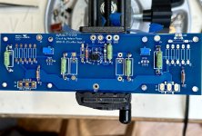
For those who already have a set of standard F5 PCBs, using the them is fairly straightforward. I have attached a photo that shows how I chose to do this. I started by following the recommended parts in the F5m BOM. This makes the job much easier. Working from the outer edges to the inner portion of the board goes like this:
R7 and R8 are 0R47, 3W wirewound
R13 and R14 are 22 Ohms, 0.5W metal film. These could be wire jumpers, but I have lots of 22 Ohm.
P1 and P2 are 500 Ohm trimpots, the design calls for 1k trimpots which would be correct for the standard grade K170 / J74. Mine are higher Idss
R9 and R11 are 270R, 3W wirewound. R10 and R12 are DNI
R3 is 22R, 3W wirewound. This location has the shortest connection to GND
R1 is 10k, 0.5W metal film. This could also be 12.4k or 15k, as it is intended to limit the input bandwidth
R2 is 47k, 0.5W metal film
The outer pins of the P3 trimpot are shorted to each other with a wire.
Input JFets Q1 and Q2 are Toshiba K170 / J74. Mine are matched with Idss at 14.2 mA. More common parts would be around 6 mA to 8 mA.
With these boards R5 and R6 are in parallel with P1 and P2, respectively. If one already has 1k trimpots, then the parallel resistors can be used if necessary to adjust the resistance for the desired Vgs across the output FETs.
I will be building the power supply mainly from parts that I already have, in keeping with the low cost objective of this project.
I have already progressed far enough with the standard F5 to F5m conversion that I will proceed in this manner. At this point, the more valuable components in the F5m essentials kit are the FETs themselves, particularly the Harris IRFP9140. My experience with alternate Fairchild and IXYS parts suggests that there are plenty of satisfactory alternatives, especially since the original F5 used Fairchild parts. I have acquired some FQA28N15 and IXTQ26P20P which appear to be a good match with one another, and also have higher transconductance figures.
For those who already have a set of standard F5 PCBs, using the them is fairly straightforward. I have attached a photo that shows how I chose to do this. I started by following the recommended parts in the F5m BOM. This makes the job much easier. Working from the outer edges to the inner portion of the board goes like this:
R7 and R8 are 0R47, 3W wirewound
R13 and R14 are 22 Ohms, 0.5W metal film. These could be wire jumpers, but I have lots of 22 Ohm.
P1 and P2 are 500 Ohm trimpots, the design calls for 1k trimpots which would be correct for the standard grade K170 / J74. Mine are higher Idss
R9 and R11 are 270R, 3W wirewound. R10 and R12 are DNI
R3 is 22R, 3W wirewound. This location has the shortest connection to GND
R1 is 10k, 0.5W metal film. This could also be 12.4k or 15k, as it is intended to limit the input bandwidth
R2 is 47k, 0.5W metal film
The outer pins of the P3 trimpot are shorted to each other with a wire.
Input JFets Q1 and Q2 are Toshiba K170 / J74. Mine are matched with Idss at 14.2 mA. More common parts would be around 6 mA to 8 mA.
With these boards R5 and R6 are in parallel with P1 and P2, respectively. If one already has 1k trimpots, then the parallel resistors can be used if necessary to adjust the resistance for the desired Vgs across the output FETs.
I will be building the power supply mainly from parts that I already have, in keeping with the low cost objective of this project.
Attachments
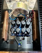
My F5m chassis work in progress. Just finishing up the power wiring before installing the channel boards.
The big copper plates were left over from a previous project that was abandoned. The transformer is a 300VA Antek AS-3222, recently pulled from my F6 chassis to allow a higher voltage substitute for that amp.
The internal dimensions of this chassis are nearly identical to the DIY VFET (lottery) chassis. Modushop had this chassis in a plain version (non VFET) for a while.
Attachments
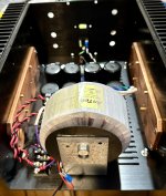
My non-kit F5m ready to begin initial power-on and bias setting procedures.
As mentioned briefly, most parts are from previous projects and stock on hand. The store F5 boards are easy to work with, as is the Universal PS board.
I have installed FQA28N15 and IXTQ26P20P FETs as indicated in one of my previous posts. The intent is to run these at higher voltage and current to find where their sweet spot lies. I expect the copper plates to offer better heat distribution. Anticipated PSU voltage is +/– 29.25V.
Attachments

Awesome, let’s see how this topology sounds! Let us know what your resulting bias current is once you settle in on it. The copper plates look sweet!
I am curious on how your choice of fets and Pa’s choice of the IRP140/9140 series will affect the harmonic spectra and the resultant sonics.
Soldering up your F6 Diamond today!
For the F5M, I’ll be using some of Prasi’s boards with these changes:

I will look into the Fets your using as well. I’m definitely curious.
Best,
Anand.
I am curious on how your choice of fets and Pa’s choice of the IRP140/9140 series will affect the harmonic spectra and the resultant sonics.
Soldering up your F6 Diamond today!
For the F5M, I’ll be using some of Prasi’s boards with these changes:
I will look into the Fets your using as well. I’m definitely curious.
Best,
Anand.

Great Class A amps always need some time to settle in. Pa’s latest is no exception.
This F5m is the first F5 that I have built, so I cannot compare it to a ‘standard’ F5. I can say that it has both remarkable flow and dynamics. It has the kind of sound that will have me reaching deeper into my library of CDs to hear things that I haven’t noticed before.
Because of my less conventional approach to this implementation, I will need to spend some extra time refining some aspects of the circuit and the power supply. The F5 boards that I used have locations for gate stopper resistors, which are currently filled with 22 Ohms. I will increase these to 110 or 120 Ohms. The input resistor which is currently 10k will probably be increased to 12.4k. These are minor tweaks that I expect to improve the voice of the amp to better suit my ears and my system.
The power supply needs a little help as well. It was originally used in the first implementation of my M2x. There is a small amount of 120Hz hum that will be dealt with. Just as importantly, it needs some help with separate filter capacitance on each channel. The stereo image is slightly less expansive than I have achieved with other recent builds. A set of motor run capacitors may solve both of those issues. The F5m circuit does have a resilient PSRR, and sounds quite good with a shared supply, but I know it can go further.
I am happy with the thermal performance of this chassis. It is dissipating about 88 Watts in each channel and has a pretty uniform distribution of heat that includes the front, rear and bottom panels.
I have developed artwork for a supply that RC filters the two channels separately which
I intend to include in the next shipment to the store. At the moment sample boards are
on their way to me. Likely we will make them available separately as well.
I intend to include in the next shipment to the store. At the moment sample boards are
on their way to me. Likely we will make them available separately as well.
Hi TA.
Really nice work. What kind of housing is that? where you got it?
Your approach is always perfect for me to follow! Thanks.
i am interested in listening comparison because your F6 was , afair, your favorite (CRLC).
kr
Chris
Really nice work. What kind of housing is that? where you got it?
Your approach is always perfect for me to follow! Thanks.
i am interested in listening comparison because your F6 was , afair, your favorite (CRLC).
kr
Chris
The chassis was from an unusual source, Aliexpress I believe, and made in China. I don’t recommend them as a seller, they have an annoying practice of spamming your email after you place an order.
Same as the one we used for the J2 prototype :What kind of housing is that? where you got it?
https://www.diyaudio.com/community/threads/firstwatt-j2.151909/post-5999278
Patrick
- Home
- Amplifiers
- Pass Labs
- Pass F5m