Ok. I am going to start off by saying that I have felt very much like an idiot the last couple of weeks while staring at my boards dreaming of sound...
About a year ago, I decided to build the F5 and the B-3 preamp. I bought the boards and stuffed most everything very quickly. Then life took over and I got sidetracked.
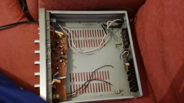
Well, a couple of weeks ago I finished my B-3 board and the Super Regulator board. I have the suggested Antek power supply. I would like to assemble these parts together in an old Radio Shack integrated amplifier case which I gutted if that is ok. It has the power switch, power cord, volume pot, and rca inputs intact.
The problem is that when I sat down to wire all of this together I realized that I have absolutely no idea what I am doing. I have replaced capacitors before and stuffed a few boards but my knowledge of electronics is beginner at best.
Is it possible to use this case with the parts that are already there? Or will it not work at all? All of the wires on the torodial transformer scared the hell out of me. Which ones go to the power switch or power cord?
I am going to try to tackle this again this weekend. And then maybe onto the F5 in a few weeks...
Any help would be appreciated.
Thanks
About a year ago, I decided to build the F5 and the B-3 preamp. I bought the boards and stuffed most everything very quickly. Then life took over and I got sidetracked.
Well, a couple of weeks ago I finished my B-3 board and the Super Regulator board. I have the suggested Antek power supply. I would like to assemble these parts together in an old Radio Shack integrated amplifier case which I gutted if that is ok. It has the power switch, power cord, volume pot, and rca inputs intact.
The problem is that when I sat down to wire all of this together I realized that I have absolutely no idea what I am doing. I have replaced capacitors before and stuffed a few boards but my knowledge of electronics is beginner at best.
Is it possible to use this case with the parts that are already there? Or will it not work at all? All of the wires on the torodial transformer scared the hell out of me. Which ones go to the power switch or power cord?
I am going to try to tackle this again this weekend. And then maybe onto the F5 in a few weeks...
Any help would be appreciated.
Thanks
Attachments
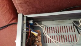
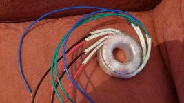
Well, it looks just like the transformer that 6l6 used. Is it Antek? If correct for BA-3 pre, primaries are the red and black wires. They go to switch, as 6l6 photos clearly show. Blue and greens are secondaries. Use continuity test with multimeter to determine the correct pairing. They go to rectifier/ power supply. Pictures show this clearly.
Wiring from power supply to board lightly more complicated but clearly dedicated.
Russellc
Wiring from power supply to board lightly more complicated but clearly dedicated.
Russellc
The red and the black wires are the primaries.
The blue and the green wires are the secondaries.
That's all I have time for at the moment.
The blue and the green wires are the secondaries.
That's all I have time for at the moment.
Tackle the F5 first, it's an easier build when using everything availible from the diyAudio store.
Last edited:
Well, it looks just like the transformer that 6l6 used. Is it Antek? If correct for BA-3 pre, primaries are the red and black wires. They go to switch, as 6l6 photos clearly show. Blue and greens are secondaries. Use continuity test with multimeter to determine the correct pairing. They go to rectifier/ power supply. Pictures show this clearly.
Wiring from power supply to board lightly more complicated but clearly dedicated.
Russellc
"Depicted" not "dedicated" flipping auto correct....
Rusellc
Hi all. I am indeed going to have to take baby steps with this but I will eventually get it. I am using the transformer that 6L6 recommended. It has two pair of red/black primaries and the two pair of blue/green secondaries.
I am still in the process of wiring the power switch/power cord/fuse section to the transformer. It looks to me like on the build guide he connects the two red wires to the positive and the two blacks to the negative of the power switch.
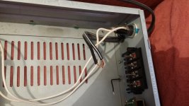
My case has a white wire running from the negative of the power switch to the fuse on the back.
Before I go any further I am going to get a grip on this. Which wires do I connect to the power cable itself? You can see on my pic above that I have two loose ends of the power cable coming into the chasis. I am assuming that I would run a wire from the positive of the switch to the positive of the cable and from the negative of the switch to the negative of the cable. Is that correct?
Thanks
I am still in the process of wiring the power switch/power cord/fuse section to the transformer. It looks to me like on the build guide he connects the two red wires to the positive and the two blacks to the negative of the power switch.
My case has a white wire running from the negative of the power switch to the fuse on the back.
Before I go any further I am going to get a grip on this. Which wires do I connect to the power cable itself? You can see on my pic above that I have two loose ends of the power cable coming into the chasis. I am assuming that I would run a wire from the positive of the switch to the positive of the cable and from the negative of the switch to the negative of the cable. Is that correct?
Thanks
oh boy
there are not positive and negative on power switch , same as no these on cable
I strongly believe that learning some basics , prior to proceeding further with build itself , will save you from wasting time and money , and especially will give you more safety while working
fiddling with mains powered gadgets is not exactly safe Lego time .
edit: just one of myriad places for start is http://www.bcae1.com/
look at menu on right side
Last edited:
Hi all. I am indeed going to have to take baby steps with this but I will eventually get it. I am using the transformer that 6L6 recommended. It has two pair of red/black primaries and the two pair of blue/green secondaries.
I am still in the process of wiring the power switch/power cord/fuse section to the transformer. It looks to me like on the build guide he connects the two red wires to the positive and the two blacks to the negative of the power switch.
My case has a white wire running from the negative of the power switch to the fuse on the back.
Before I go any further I am going to get a grip on this. Which wires do I connect to the power cable itself? You can see on my pic above that I have two loose ends of the power cable coming into the chasis. I am assuming that I would run a wire from the positive of the switch to the positive of the cable and from the negative of the switch to the negative of the cable. Is that correct?
Thanks
Do one step at a time.
Take a picture of each step and ask for confirmation.
Look at the powersupply schematic a million times and look at a few of the 6L6 build threads eg F4, F5 etc.
Check IEC socket wiring too (google is your friend)
Once you've completed the power supply wiring get someone to properly check your work.
Thanks guys. I am not going to fire anything up without taking and posting pics for confirmation. I am going to spend some time this week reading about transformers and power socket wiring. I will work on this more after I have read more about it.
Thanks
Thanks
transformer with 22vac or 24vac secondaries should work. I'm also going to use the super regulator boards for a ba-3 preamp build. 6L6 used a different regulator in his build guide that has the rectifiers and the filter caps together on the same board. The super regulator doesn't have them. So if you don't have them you will have to buy them.
It is recommended to supply the super regulator with a voltage that is at least 6vdc higher than the regulated output. So if you want 24vdc out of your regulator, a
There are some very good animated circuits online with audio showing how full wave rectification works. It makes it very easy to understand how AC is changed to unregulated DC.
transformer with 22vac or 24vac secondaries should work. I'm also going to use the super regulator boards for a ba-3 preamp build. 6L6 used a different regulator in his build guide that has the rectifiers and the filter caps together on the same board. The super regulator doesn't have them. So if you don't have them you will have to buy them.
It is recommended to supply the super regulator with a voltage that is at least 6vdc higher than the regulated output. So if you want 24vdc out of your regulator, a
There are some very good animated circuits online with audio showing how full wave rectification works. It makes it very easy to understand how AC is changed to unregulated DC.
this is the new version of what 6L6 used, I used it in one of my BA-3 preamps and it works great, just order 24 volt version, and I went with the larger size heatsinks,2.5 inches I believe? It fits the chassis 6L6 used perfect.
GlassWare PS-19 Bipolar Power Supply Kit
Russellc
wendelltate,
Here's my 2 cents. Not trying to state the obvious, but try the following.
Keep in mind that the power supply and amp circuits are separate units, even if you are placing them in one box. Build and test the power supply first. Without a good working power supply, the amp circuit is at best useless and at worst potentially damaged by a bad power supply.
Build the power supply first. Establish what those parts are and how they fit together.
Look through First Watt "F" series articles for a power supply schematic. F4 article definitely has one. FIRST WATT. Take the parts, lay them out with the power supply schematic and stare at them over and over. Do this before soldering anything.
Also, have all the physical parts on-hand to visualize the build.
Here's the catch. You will need to decide how some parts connect to each other. Not everything is soldered together as can be seen in the 6L6 build guides. A lot of the boards interconnect via barrier strips or Euro connectors. If using barrier strips, you'll want to use crimp on connectors on the end of the power supply wire leads. Euro connector barrier strips accept bare wire.
I get loop and spade connectors from Home Depot because I know they are at least copper and not super expensive. They are not gold plated, but they are at least tinned.
Use a soft, multi-strand wire of a good gauge, like 14 or 16 gauge, Don't go crazy with 10or 12 gauge right now. Aside from not being always necessary, it's harder to work with when you first start out. This is just my opinion. Also, avoid solid core (one conductor) wire in a power supply. It's not as safe as multi-strand.
Wiring up the amp circuit is another story, but you'll do the same as the power supply.
Lay everything out and visualize it over and over until it makes sense.
One last thing. Try to understand the difference between power ground and signal ground. How do they interact? What is star-ground? Ground loops can be tricky to fix, so get a good grip on grounding schemes.
Hope this helps. Any questions, just ask.
Vince
Here's another tip, if not mentioned before.
When looking at the transformer primary and secondary wiring, use a DMM set to continuity or low resistance measurement to test which leads are pairs.
So, on the primary side, take one lead and connect the red probe to it.
Take the black probe and touch the remaining leads.
The pair will read 0 (zero) ohms if using resistance setting or hear a tone when they are a pair.
Mark them with tape.
Use the manufacturers key to know which is 120v and the other is 0v.
Now with that knowledge, look at the power supply schema and see how they fit into the power supply primary side build. You can do the same for the secondary side of the transformer.
Hope this helps,
Vince
Use the boards you have to draw a template with them. Outline the perimeter and where the stand-off holes are, even draw some of the parts to mark board orientation.
Use the templates to see where you want the parts to go in the case. It's not a good idea to handle the built boards and place them flat on a metal surface.
Also, be careful when handling active components such as jfets, mosfets and diodes and any part really. Static discharge from your body can kill a part. Ground yourself before touching parts. Lookup the best way to do this. Some use a wrist grounding strap to grounding themselves.
Last edited:
- Status
- Not open for further replies.
- Home
- Amplifiers
- Pass Labs
- Pass B-3 preamp build (sort of)