I also have oversized (120VA) transformers and ended up adding power resistors to drop the voltage ahead of the regulators to help the reg caps.
Do you have the BOM list for your boards ? Or a link to the BOM ?
Easy enough to swap the transformer to the front.
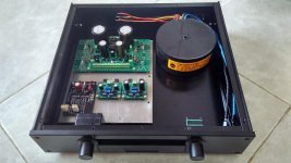
The original P1.7 only had a single PSU.
The transformer is a 120VA unit.
The original P1.7 only had a single PSU.
The transformer is a 120VA unit.
Last edited:
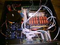
here is my layout of the P1.7. did someone say oversized transformer? 🙂 ended up using a 160VA.
Love that encapsulates talema 😀 I also wanted to use 160VA for dcB1 but it's taking too much spacr, finally ended with 50VA
Attachments

sorry no BOM. the preamp is a stock version as per Papa schematic. relays, caps and resistor footprints were all called out early in this thread. just go back and read through it.
sorry no BOM. the preamp is a stock version as per Papa schematic. relays, caps and resistor footprints were all called out early in this thread. just go back and read through it.
Is it part for part ? If it is i can use the original schematic..
Aaaaargh, still haven't started on this one!
The upside is that I moved and now have my own mancave 🙂
Good things come to those who wait??? Or something like that....
Cheers!
The upside is that I moved and now have my own mancave 🙂
Good things come to those who wait??? Or something like that....
Cheers!
Hi folks
What are you all using for relays in the aleph P? I've never built an attenuator with relays, always having used switches in the past.
What are you all using for relays in the aleph P? I've never built an attenuator with relays, always having used switches in the past.
Gee, mine is almost a year old now! Went together flawlessly and works great. With the amplifier's I have here... Aleph 2, KSA-50, Phase Linear 700 it is also quiet enough that I did not bother with a complex and ridiculous stepped attenuator on the output but rather a simple stepped attenuator on the input. My speakers (Dynaudio) are about 89db efficient. So what ever noise there is it certainly is inaudible with my ears right next to the tweeter.
Mark
Mark
Hi Mark. I've experimented before with output attenuation and want to do the same with the P. I think I'm going to put together 1 channel and experiment with the output attenuator values on a breadboard to see what functionality I may need. Perhaps something with fewer steps would do the job, thus making the construction simpler.
The attenuator isn't really that complex and is rather ingenious actually. It always resolves down to 2 resistors in a voltage divider. This topology can be used due to the current output design of the P.
The attenuator isn't really that complex and is rather ingenious actually. It always resolves down to 2 resistors in a voltage divider. This topology can be used due to the current output design of the P.
The one I used is here.... It's very inexpensive, has high quality resistors and works well. I believe I used a 50K unit on the input side, but I'd have to actually dig up the instructions again to see...
Balanced Strereo Attenuator
Mark
Balanced Strereo Attenuator
Mark
I've got a 4 GANG 10K Audio Log pot for a volume control.
Should it be at the input of the P1.7 or the output ?
Should it be at the input of the P1.7 or the output ?
Pass put them at the output but that seems sort of high resistance to use there. I confess I do not remember the stacked resistance of the factory fader.
I put my 50k stepped attenuator at the input, however some people say this preamp is not as quiet as others. The noise heard is going to depend on the efficiency of your speakers, mine not being very efficient. I would experiment first and try yours both ways. First on the output since that's the intended place, and if that doesn't work then on the input. 10k is a fairly low resistance for input. Some pieces of gear may not like it.
Mark
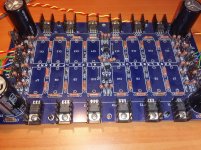
A friend of mine started on a P1.7 build years ago but never completed it. I got the boards (KK amp + psu boards) but only have one functional channel (when I put a 1KHz 1Vpp sine on input, I get a 1KHz sine on output of channel A, but nothing on channel B). It turns out to be more difficult to find the error than I had hoped.
The PSU boards (dual mono setup) are in a separate enclosure and I have just under 60V on both boards, also when amp board is attached, so assume that there is no problem with the PSU.
I noticed that my friend had used IRF630 rather than IRF610 and understand these give a darker sound but should work in this amp (I will leave them on the board for now and may change to IRF610 sometime in the future).
I have measured some voltages (ref. to GND) and the non-functioning channel has some odd readings. I have checked all values of resistors etc. against KK's part list but have not found errors. My friend used Audyn-Cap MKP-QS 400V caps that are too large for the board. They are removed in order to check values (see photo).
As I had heard that ZTX450 and ZTX550 have caused problems in other builds I changed these but the readings stay the same.
The readings I get (left is functioning channel, right is defunct channel) are in the attached PDF. Schematic below (no part numbers on schematic).
Anyone have any suggestions what to check?
Thanks,
Albert
Attachments
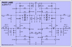
It's a bit hard to equate your transistor numbers to the schematic I have. It looks to me that there is a problem with the circuitry around the Ztx450 and the bottom 610. The source of the 610 should be at the same potential as the base of the 450. There is only a 221 ohm resistor between them. Check the connections in that area. The voltage should be roughly .6-.7von the base and at the source of the 610. You have 5.26 on the source. check the connections with an ohm meter.
I've got a 4 GANG 10K Audio Log pot for a volume control.
Should it be at the input of the P1.7 or the output ?
10K should be used at the output.
It's a bit hard to equate your transistor numbers to the schematic I have. It looks to me that there is a problem with the circuitry around the Ztx450 and the bottom 610. The source of the 610 should be at the same potential as the base of the 450. There is only a 221 ohm resistor between them. Check the connections in that area. The voltage should be roughly .6-.7von the base and at the source of the 610. You have 5.26 on the source. check the connections with an ohm meter.
Hi Bfpca,
Just in case there was a bad solderjoint somewhere, I reheated all solder joints.
I have visually checked all resistors and then checked all with a ohm meter in situ and found no differences between the channels. I even took out a 680pF silver mica to check (it was fine).
I am wondering if it could be a faulty irf9610 or irf630. Any ideas how to check?
Thanks,
Albert
It's a bit hard to equate your transistor numbers to the schematic I have. It looks to me that there is a problem with the circuitry around the Ztx450 and the bottom 610. The source of the 610 should be at the same potential as the base of the 450. There is only a 221 ohm resistor between them. Check the connections in that area. The voltage should be roughly .6-.7von the base and at the source of the 610. You have 5.26 on the source. check the connections with an ohm meter.
I just checked resistance in situ from ztx450 base to irf630 source and found all values on both channels about 221R as expected.
- Home
- Amplifiers
- Pass Labs
- Pass Aleph P 1.7 preamp builders thread