Hi Everyone,
Earlier this year, I was fortunate enough to purchase an original 1996 vintage Aleph 5 amplifier. It was described as being in working condition, but since it was located in another city, I couldn’t test or inspect it in person. I only recently got my hands on it.
When the amp arrived, it was freezing cold, so I knew it wasn’t safe to power it on immediately. In my excitement, I decided to take a peek under the hood, which led me to remove the side heat sinks so I could get the top off. Since I’d already planned to replace the original, aging capacitors, I decided to proceed with the upgrades.
I replaced the original Pani 220uF capacitors with Silmics, adding 1uF Wima bypasses, and I swapped out the four original 33,000uF cans for new 47,000uF ones.
At this stage, I noticed something concerning: the fuse holder showed signs of excessive wear, and instead of the factory-specified 4A slow-blow fuse, a 6A slow-blow fuse was installed. It dawned on me that I might have made a rookie mistake—modifying the amp before confirming that it was actually functioning. With that realization, I reassembled everything, triple-checked all the connections and capacitor orientations, and prepared to test the amp. For what it’s worth, I didn’t see any signs of damaged components or previous repairs inside.
For testing, I powered the amp using a dim bulb tester with a 100W bulb and connected a pair of multimeters to monitor the DC offset at the speaker outputs. I understand that a class A amplifier will typically keep the bulb brighter than a standard amp, making it harder to interpret the results.
On powering up, the bulb initially went bright, briefly dimmed, and then brightened again. The real concern was the multimeters showing large amounts of DC at the outputs, prompting me to immediately shut everything down. I wasn’t able to catch the exact peak DC values because of the quick shutdown, but as the power supply discharged, the meters both showed around 1V DC for an extended period.
This brings me to the part where I’d appreciate some guidance. I’m thinking of disconnecting the output stages from the main board to isolate the issue. This would let me test the power supply voltages and determine whether the front end is feeding DC to the outputs, helping narrow down which section of the amp is causing the problem.
Does this troubleshooting approach sound reasonable? Or is there a chance that my testing process itself was flawed?
Thanks in advance for your advice!
bulb tester is fooling with ya, keeping amp voltage starved
install proper mains fuse, power it on
inputs shorted, no load
inform here what DC offset and Iq
expect 500mV to 670mV across 1R source resistors
be sure to check torque of mosfet screws, same as thermal goop condition
install proper mains fuse, power it on
inputs shorted, no load
inform here what DC offset and Iq
expect 500mV to 670mV across 1R source resistors
be sure to check torque of mosfet screws, same as thermal goop condition

Thank you Zen Mod, you are were quite correct that the DBT was messing with my Aleph's mojo. Without your help I might have spent days taking things apart and testing them.
So the amp powered up and DC offset quickly settled at 11mv and 27mm which is great. What was interesting is that after powering down I read1 .3v and 1.2v, is that normal?
One thing I didn't mention before is that the original CL-60 was looking rather cooked, so I changed it out for new one when I replaced the caps.
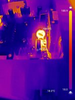
I decided to test out my nifty new thermal camera just now, and discovered the new CL-60 was reading 188.9c after just a few minutes of operation (with no cover in place). Does that temp suggest the amp is pulling too much current? I did bump the PS filters from 31,000uF to 47,000uF. I didn't measure the bias across the source resistors yet, but can do so next if assuming the CL-60 isn't a cause for concern. I see discussion elsewhere in this forum of upsizing the CL-60 to a SL-70 or SL15-60002.
Thanks once again.
So the amp powered up and DC offset quickly settled at 11mv and 27mm which is great. What was interesting is that after powering down I read1 .3v and 1.2v, is that normal?
One thing I didn't mention before is that the original CL-60 was looking rather cooked, so I changed it out for new one when I replaced the caps.
I decided to test out my nifty new thermal camera just now, and discovered the new CL-60 was reading 188.9c after just a few minutes of operation (with no cover in place). Does that temp suggest the amp is pulling too much current? I did bump the PS filters from 31,000uF to 47,000uF. I didn't measure the bias across the source resistors yet, but can do so next if assuming the CL-60 isn't a cause for concern. I see discussion elsewhere in this forum of upsizing the CL-60 to a SL-70 or SL15-60002.
Thanks once again.
Attachments
after powering down I read1 .3v and 1.2v, is that normal?
normal for Aleph
with load it'll be much less
Thanks for the assistance, my Aleph has been playing for a few hours now and it sounds great. Heat sink temps are 55-58 degrees in my 22 degree room.
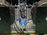
I leave the component leads long, sleeved w/ teflon tubing to allow for some breathing space since this part does run hot in a Class A amp by design. I don't have a decent picture of mine but here's an example from one of ZM's amps, I suspect he doesn't mind me sharing (stealing) this snip..the original CL-60 was looking rather cooked, so I changed it out for new one when I replaced the caps.
Attachments
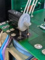
Thanks William, I changed the new CL-60 out for a SL15 60002 which I left high above the board, and bent over away from the X type cap. The SL15 60002 still gets really hot, I might grab a SL32 5R020 on my next parts order and try it out. I'll see if I can order some suitable high temp wire sleeve too.
I'm curious if there's a reason to leave these varistors in the circuit full time? I appreciate the soft turn-on they provide, but, other than the extra complexity, is there a good reason not to have a relay short them after a few seconds? I guess they're essentially forming an R-C filter, with the supply filter caps, but any other reason to not bypass them?
I guess it's just a simple solution that works well enough. I bypass the thermistors in my monoblocks manually with a secondary switch a few seconds after the primary switch. I've done this technique / power up procedure for over twenty years now on these amps. I suspect most people hold their nose and point at me for doing such a thing... because I've never seen or heard of anyone else with a similar uber simple setup. Everyone either does the supernova hot TH in operation, or a "proper" supplemental timed relay whatever whatever PCB mounted somewhere.
well, pretty much best soft start is (appropriate string of) NTC(s), bypassed with delayed relay
if done properly (fast recovery time of delay), it gives protection even from blackout
blackout being pretty much most critical situation for permanent connected NTC, enough time to drain cap bank, but not enough time for NTC to cool down
if done properly (fast recovery time of delay), it gives protection even from blackout
blackout being pretty much most critical situation for permanent connected NTC, enough time to drain cap bank, but not enough time for NTC to cool down
I did that with my dual mono Aleph J. I used 3 CL-60's in series for each channel.
An adjustable time delay relay trips (15 sec) another heftier relay to by-pass the CL-60's.
Mains voltage into the x-formers starts at about 70V then ends up close to actual mains voltage at switching.
I've logged a few hundred hours on the amp with zero issues. Provides a very soft and smooth start every time.
Hope this helps 🙂
Why not simply install a 115/230V relay behind the NTC (coil parallel to the transformer) that shorting the NTC.
That would indeed be simpler but most 120V/240V relays I've dealt with engage well before they reach their
rated voltage making them unpredictable. YMMV
BTW I like your signature photo. I've got an M235i that I love.
rated voltage making them unpredictable. YMMV
BTW I like your signature photo. I've got an M235i that I love.
Hello. I'm thinking about building Aleph 5. My question is about the accuracy of the transistor pairing, what should be the accuracy of the selection? If it's a bad section, I apologize. Greetings Piotr F.
Hi Piotr, if you search the forums for "Mosfet matching" you should find the information you're after. A good example is the following thread:
After building a couple of multi-output device MOSFET amps, I noticed that the current draw between the devices can vary wildly sometimes. Good thing for source resistors to allow load-balancing. I knew this was happening because I did not have Vgs matched resistors. So how to match them - I looked around for awhile on these threads but nothing jumped out as an easy to do HOWTO guide.
So here is the guide for dummies like me - I will call these threads the "Easy Peasy" (TM) threads. You may have seen the similar titled Juma's Easy Peasy Cap Multiplier thread. So I...
So here is the guide for dummies like me - I will call these threads the "Easy Peasy" (TM) threads. You may have seen the similar titled Juma's Easy Peasy Cap Multiplier thread. So I...
- xrk971
- Replies: 39
- Forum: Solid State
- Home
- Amplifiers
- Pass Labs
- Pass Aleph 5 troubleshooting