Its been a while (about 1.5yr) since I have built any amps, but I have had some parts burning a hole in my closet that required me to get off my butt and do something with.
What I built was a fully regulated 300B amp using a 6C45n driver tube CCS loaded into a power drive then into the 300B. I know of the mixed reviews of the 6c45n but I have them and I wanted to see if I could tame it. The OT is temporarily a Edcor XSE 15-8-5K and I am pushing 80mA bias @375V. The 6c45n is 150V at 15mA.
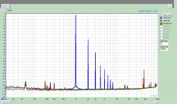
I have never really measured a SE amp so I am curious of others perspective of the results. The amp sounds nice but the measurements are ? I am happy with the noise floor however. at 1Watt(2.82V into 8R) i measured 1.004% THD. Is this pretty normal for a 300b SE? I would think there is alot I could do to make it better. The freq responce is 27(-3dB) to 90k(-1dB).
After working with my mullards, I have no feel for what would be good.
Thanks for your insight
What I built was a fully regulated 300B amp using a 6C45n driver tube CCS loaded into a power drive then into the 300B. I know of the mixed reviews of the 6c45n but I have them and I wanted to see if I could tame it. The OT is temporarily a Edcor XSE 15-8-5K and I am pushing 80mA bias @375V. The 6c45n is 150V at 15mA.
I have never really measured a SE amp so I am curious of others perspective of the results. The amp sounds nice but the measurements are ? I am happy with the noise floor however. at 1Watt(2.82V into 8R) i measured 1.004% THD. Is this pretty normal for a 300b SE? I would think there is alot I could do to make it better. The freq responce is 27(-3dB) to 90k(-1dB).
After working with my mullards, I have no feel for what would be good.
Thanks for your insight
Attachments
It sounds decent because of the distortion's spectral distribution.
Post a schematic, please. Maybe combination bias, without a bypass cap. on the cathode resistor, can be employed. That would linearize the 300B.
Post a schematic, please. Maybe combination bias, without a bypass cap. on the cathode resistor, can be employed. That would linearize the 300B.
I will get a schematic up after the next day or so. I have to put my toy away to finish up some school work before spring break. I also want to get a few more measurements as well, particularly of the driver.
Its been a while so I am rusty on the test equipment which is why I posted such a lousy looking spectrum. Is that a normal harmonic distribution and magnitude for a 300B?
Its been a while so I am rusty on the test equipment which is why I posted such a lousy looking spectrum. Is that a normal harmonic distribution and magnitude for a 300B?
Its been a while so I am rusty on the test equipment which is why I posted such a lousy looking spectrum. Is that a normal harmonic distribution and magnitude for a 300B?
For a VT like the 300B, single-ended, that's a normal harmonic profile. Looks pretty good, what's called a "waterfall" distribution. You could improve on the harmonic distortion performance by including a higher quality (more $$$$) OPT and/or applying gNFB. Some SE designers/users would consider the latter "heresy". You've already gone heretical by including SS in the design, so why not wrap some gNFB around that 300B?
It's also a good thing that you opted for the "power drive" topology. Lots of complaints about less than stellar sonics from 300B's stems from inadequate grid drive. Power triodes like the 300B present the driver with a less friendly load than pents, due to the higher reverse transfer capacitance that gets magnified by Mr. Miller, the presence of grid current even before Vgk actually goes positive, and the much larger input swing. If you don't take that into consideration when designing a driver, you're likely to be disappointed with the end result.
Is that a normal harmonic distribution and magnitude for a 300B?
Distribution yes, magnitude no. 1% at 1W and 1KHz is a bit high.
The simplest 300B amp I have seen used a 12AX7 with the two sections in parallel and self-bias. That's something I would never built..!!
However the max Pout was close to 10W and THD surprisingly low: 0.1% at 1W and less than 2% at 8W! Some harmonic cancellation led to such result. The sound was not bad at all. Not my favorite but surely better than one might think...
Thanks for the feedback, 45, Eli and Miles. Have a little time to play so worked on my measurement system and came up with the attached. 0.39% THD+Noise is a much more realistic number. IMD appears to be a bit high so need to look at OPT and Ht regulators. Blue is Output at 1 Watt into 8 ohm, the red is the driver signal into the 300B offset bu 14dB
The IMD surprises me. Curious to see if OPT or regulator is responsible Schematic soon.
The IMD surprises me. Curious to see if OPT or regulator is responsible Schematic soon.
Attachments
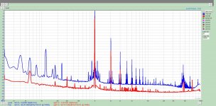
The IMD doesn't surprise me at all. It's 120 Hz ripple mixed with your signal frequency (and its harmonics). If you aren't already using well-regulated DC supplies for the B+ and the 300B filament supply, I strongly suggest that you implement those.
In my 300B amp (see my website), I use a 6N6P driver tube. I get about 0.18 % THD at 1 W, 3 % THD at 11 W.
~Tom
In my 300B amp (see my website), I use a 6N6P driver tube. I get about 0.18 % THD at 1 W, 3 % THD at 11 W.
~Tom
Thanks Tom. After I posted the original spectrum, I saw the distortion value of your amp and have been using them as a benchmark for this project. I still have some quirks to work out on my measurements as this is a well regulated HT and B+. In fact it should be no different than your amp as it uses the same regs. B+ is a C-L-C-(21 madia)-C.
I am not sure what the best measurements will be yet, I plan to work on optimum driver bias and then refine the output stage.
I'll post a schematic today if I get enough time.
I am not sure what the best measurements will be yet, I plan to work on optimum driver bias and then refine the output stage.
I'll post a schematic today if I get enough time.
Thanks for the feedback, 45, Eli and Miles. Have a little time to play so worked on my measurement system and came up with the attached. 0.39% THD+Noise is a much more realistic number. IMD appears to be a bit high so need to look at OPT and Ht regulators. Blue is Output at 1 Watt into 8 ohm, the red is the driver signal into the 300B offset bu 14dB
The IMD surprises me. Curious to see if OPT or regulator is responsible Schematic soon.
I think that most of that IMD is caused by the 300B filament supply as it is nearly absent in the driving signal, in comparison.
P.S.
I was assuming that your filament supply is already DC. If not you should do it, in my opinion.
On the other side it is also true that your driver is CCS loaded so, let's say, it is less demanding in terms of HT supply. Anyway IMD overall is not bad at all. The main peaks around 1KHz are at -90 dB! You could see how it looks at higher output. Sometimes people don't see it because they don't have enough resolution.
Last edited:
45, it is a regulated DC using tomchr's universal filament supply. and TheGimp you are right, the B+ madia did not have enough operating headroom. Problem corrected on this plot.
I need to switch out my OPT's though. I am highly suspect that they are not as labeled. Is there an easy way to measure them? I am pushing 120mA to get the THD to 0.36%. At 100mA it jumps back up to 0.7%
I need to switch out my OPT's though. I am highly suspect that they are not as labeled. Is there an easy way to measure them? I am pushing 120mA to get the THD to 0.36%. At 100mA it jumps back up to 0.7%
Attachments
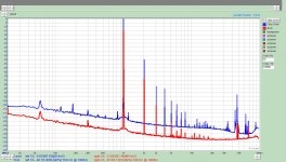
I need to switch out my OPT's though. I am highly suspect that they are not as labeled. Is there an easy way to measure them? I am pushing 120mA to get the THD to 0.36%. At 100mA it jumps back up to 0.7%
Generally 100 mA is the max anode current for a 300B with fixed bias. Your OPT has to be really wrong if you have to go up to 120 mA to decrease by that amount the THD at just 1W. The easy way is to put through the primary a voltage and see what you get at the secondary (it will be affected by the insertion loss that you can evalutate measuring the DCR as insertion loss is number referred to 1KHz unless specified otherwise). This sounds wierd to me and I would not rule out the possibility of a less linear than average 300B.....
45, it is a regulated DC using tomchr's universal filament supply. and TheGimp you are right, the B+ madia did not have enough operating headroom. Problem corrected on this plot.
That makes more sense. Nice plot! I'm guessing the 1 kHz +/-180 Hz components originate from the signal source.
I need to switch out my OPT's though. I am highly suspect that they are not as labeled. Is there an easy way to measure them? I am pushing 120mA to get the THD to 0.36%. At 100mA it jumps back up to 0.7%
I'm running 400 V, 85 mA on JJ 300B tubes using 6N6P for the driver. I have no trouble getting below 0.2~0.3 % THD.
I'm not sure what you mean by the OPTs not being labeled. You said earlier that they are Edcor XSE15-8-5k, so at least the pinout of the transformers should be well known. As others have mentioned, you can measure the turns ratio by applying an AC voltage on the primary and measuring the secondary voltage. For a 5k:8 transformer, the impedance ratio is 5000/8 = 625:1, so the turns ratio should be sqrt(625) = 25:1.
I have spent over two years researching and prototyping my 300B driver circuit. The 300B is not an easy tube to drive. The driver needs to provide nearly 200 Vpp swing at low distortion and have a low output impedance. This is a rather tall order. The driver I designed can deliver the goods.
Among other tubes I've tried, have been the 5842, 6SN7, 6SL7, and others. The THD with those tubes was 0.6~1 % (1 W, 1 kHz) and the sound quality somewhat 'stuffy' of muddy.
~Tom
Red is the driver signal at the grid of the 300b. The small 60Hz seen from both is the 1616m sound card. The 180Hz seen at the output is unknown at this point. I still need to post a schematic.
FYI tested the tranny and it is spot on at 25:1. Redoing the bread board to clean up a few things. After having a little time to think about the results so far, I am now suspicious that the bias current I am measuring may have another load beside the 300b bias included. I don't see it looking at how it is wired but a good look is in order.
As it is wired now, the 120mA (assuming that it is really 120mA) doesn't even phase the tube.
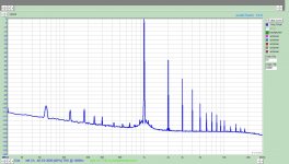
Purchased some JJ 300b's. Much Better!!!. Still some work but at least in the ball park now. Attached graph is 380V at 80mA bias. The 60Hz peak and harmonics is from measurement system, as I can see the same with power off.
Bias Current was spot on so no sneek circuits in the loop.
edit. Plot is 0dB= 1Watt
Bias Current was spot on so no sneek circuits in the loop.
edit. Plot is 0dB= 1Watt
Attachments
Last edited:
Careful with the high bias currents. With fixed biased, JJ's "spec" says 100 mA max. You can go to 160 mA with auto-bias. Still... Obey the 42 W max plate dissipation.
~Tom
~Tom
I thought 80mA bias was within its safe range? Thats 30 Watts on the plate.
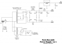
I am finally getting around to post able schematics. This is how the power supply is built currently. The 300b uses the Universal filament regulator and the 6c45 uses a LM317 in constant current mode. I have those on the amp schematic I am working on now but will probably add them to the PS schematic.
I am finally getting around to post able schematics. This is how the power supply is built currently. The 300b uses the Universal filament regulator and the 6c45 uses a LM317 in constant current mode. I have those on the amp schematic I am working on now but will probably add them to the PS schematic.
Attachments
Max cathode current for the JJ 300B is 100 mA in fixed bias; 160 mA in cathode bias. So, yes, 80 mA is safe.
I run 80~85 mA, 400 V on my JJs. I'm playing a bit with the operating point these days. Just to see how it affects the tone.
In a previous post you mentioned 120 mA. Hence my post above (#17).
~Tom
I run 80~85 mA, 400 V on my JJs. I'm playing a bit with the operating point these days. Just to see how it affects the tone.
In a previous post you mentioned 120 mA. Hence my post above (#17).
~Tom
Last edited:
- Status
- Not open for further replies.
- Home
- Amplifiers
- Tubes / Valves
- Parts Box 300b