There should be a switch on the amp backside to select XLR or chinch.Not sure what you mean on the input switch.
I’ll pull D6 and test it.
I can run to a local electronics store that should have a 5W or higher resistor.
I can run to a local electronics store that should have a 5W or higher resistor.
I think it is ok to test in circuit. That includes the parallel connected blue film caps.
I ask about possible short because the resistor could have been a secondary failure.
But normally the difference in power dissipation between 99V and 99V - 15V = 84V should not be an issue.
Maybe it was just a bad part.
I ask about possible short because the resistor could have been a secondary failure.
But normally the difference in power dissipation between 99V and 99V - 15V = 84V should not be an issue.
Maybe it was just a bad part.

What would D6 be. I’m heading to get a new 2.7k resistor and could buy one just to have on hand.
From the schematic, it is 15V / 1Watt. But if there is no short, you only need the resistor.
If you can not find the right one, something like 2x 5.6K 3W parallel will do it too.
If you can not find the right one, something like 2x 5.6K 3W parallel will do it too.
Avoid removing parts for testing when it isn't necessary.
That could do further damage. Test in-circuit unless it is not possible.
That could do further damage. Test in-circuit unless it is not possible.
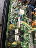
Just a 'shot in the dark' here - but TVR3 is also looking somewhat 'uncomfortable' (brown), right next to R93
I think it just has a brown plastic top.Just a 'shot in the dark' here - but TVR3 is also looking somewhat 'uncomfortable' (brown), right next to R93
Do not touch any of the pots. If any adjustments are necessary later, take a close up picture before misaligning anything.
We do not have a manual...
Good news. I popped in the $1.50 resistor and we have a relay click! This was the only 2.7k resistor they had over 5 watts and under 25 watts.
Confirmed -15V at pin 4 of the opamp and the Drain voltages on Q5 and Q6 now match the other channel!
I confirmed D6 was not shorted as well.
No DC offet at the outputs.
I plugged in some junk speakers and the music is playing on both channels!!
Confirmed -15V at pin 4 of the opamp and the Drain voltages on Q5 and Q6 now match the other channel!
I confirmed D6 was not shorted as well.
No DC offet at the outputs.
I plugged in some junk speakers and the music is playing on both channels!!
Attachments
I think I want to check the bias next. The right channel feels to be warmer but that could be because it didn’t have the same airflow being crammed on my workbench with the left channel having all the breathing room. I moved it and letting it warm up some more.
Congratulations, very nice. 
Eventually resolder the right side of the resistor, it looks like the wire is still blank but could be ok too.
Eventually resolder the right side of the resistor, it looks like the wire is still blank but could be ok too.
The AD711 could not work without the negative rail and instead of keeping the output at zero, it caused the high offset voltage.Confirmed -15V at pin 4 of the opamp and the Drain voltages on Q5 and Q6 now match the other channel!
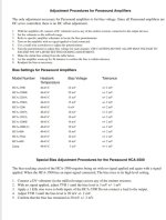
So just compare the voltages across a 0.22 ohms resistor on the two channels, after warm up.I think I want to check the bias next.
Yes. Makes complete sense. Thanks for all the help!!
The right channel is about 47 degrees Celsius while the left channel is 40 degrees. I measured across one of the Emitter resistors on both sides and the left is definitely lower than the right. Its 1 MV while the other is 3MV without a signal.
I’m following the below.
The right channel is about 47 degrees Celsius while the left channel is 40 degrees. I measured across one of the Emitter resistors on both sides and the left is definitely lower than the right. Its 1 MV while the other is 3MV without a signal.
I’m following the below.
Attachments
I knew you could do it Dustin! Nice work to all those who helped! Very impressive how this was done from so many folks invested to help and support from all over. Generosity to the rescue. I'm inspired.
arg. I think I moved to quick and accidentally adjusted TVR 2 and not TVR 3 when doing the second step.
Any idea the purpose of TVR 2?
Any idea the purpose of TVR 2?
- Home
- Amplifiers
- Solid State
- Parasound HCA 3500 -- Part it out or Get it fixed?