Hi all,
I received a "new" Parasound D/AC 1000 Dac based on PCM63 Dac chips, after comparing it to my other Dacs and CD players (AD1862 Diyinhk, Orelle DA188, Philips CD151, Yamaha CDX-630E) it feels like it's output level is much higher than all the others so I measured it's output level using a multimeter (Vac RMS) while playing 1khz 0db test tone and the multimeter shows 3.1 Vac out put while all my other devices measured around 2Vac (as they should).
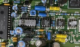
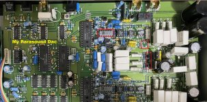
I opened it's cover and it seems like that Parasound "over built" it in comparison to other Dacs that I have/had.
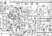
I have the Parasound Dac1000 schematics and I would like to know please how can I lower the output level to (standard) 2Vac output to match my other sources level.
There is a little difference in the Dac1000 that I have and the Dac1000 schematics, in the schematics the I out is connected to an AD744 opamp and in my Dac it's connected to AD841, and in my Dac there are no C304/C404, in the schematics there are 5534 opamps that are missing in my Dac but there are AD817 opamps.
Any help will be appreciated.
Thanks
I received a "new" Parasound D/AC 1000 Dac based on PCM63 Dac chips, after comparing it to my other Dacs and CD players (AD1862 Diyinhk, Orelle DA188, Philips CD151, Yamaha CDX-630E) it feels like it's output level is much higher than all the others so I measured it's output level using a multimeter (Vac RMS) while playing 1khz 0db test tone and the multimeter shows 3.1 Vac out put while all my other devices measured around 2Vac (as they should).
I opened it's cover and it seems like that Parasound "over built" it in comparison to other Dacs that I have/had.
I have the Parasound Dac1000 schematics and I would like to know please how can I lower the output level to (standard) 2Vac output to match my other sources level.
There is a little difference in the Dac1000 that I have and the Dac1000 schematics, in the schematics the I out is connected to an AD744 opamp and in my Dac it's connected to AD841, and in my Dac there are no C304/C404, in the schematics there are 5534 opamps that are missing in my Dac but there are AD817 opamps.
Any help will be appreciated.
Thanks
Attachments
You could replace R311 and R411 with voltage dividers with an output resistance of 6.04 kohm.
That is, change it to R311 = R411 = 9.31 kohm and add 17.4 kohm resistors to ground from the point where they are connected to R312, R313 or R412, R413.
That is, change it to R311 = R411 = 9.31 kohm and add 17.4 kohm resistors to ground from the point where they are connected to R312, R313 or R412, R413.
Last edited:
Thanks, will try and report.
Can you please explain what is the purpose of each the opamps after the Dac output?
Can you please explain what is the purpose of each the opamps after the Dac output?
Overall it's sound is dynamic and detailed
(to my ears of course in my system which include Wiim mini, JBL L1 speakers and Rega Elex-r amp, will try later with my Dynaudio Focus 110)
but in comparisson to my other devices it feels like it's missing the lower mids a bit and there is a little bit of "roughness" in the high frequencies which not presented in my other sources that I would like to remove or smooth, any suggestions?
What really surprises me is the absence of C304 and C404. Particularly at high audio frequencies, it may lead to slew rate limiting in IC306 and IC406. If I wanted to modify the DAC, the first thing I would do would be to mount some decent quality 1 nF capacitors there, decent quality meaning preferably polystyrene, polypropylene or ceramic class 1 (such as NP0, C0G), most certainly not ceramic class 2 (such as X7R, X5R, Y5V, Z5U).
Regarding the function of the op-amps:
IC306 and IC406: current to voltage conversion, current to voltage conversion combined with a part of the reconstruction filtering when C304 and C404 are mounted.
The + and - signs in the symbol of IC302 are swapped.
IC302 and IC402: buffers after the switchable de-emphasis networks R305, R306, C316 + C317 and R405, R406, C416 + C417
IC303 and IC403: I think these must be frequency-dependent negative resistance circuits, part of the reconstruction filter.
R311, the circuit around IC303, R312 and C323 form a third-order low-pass filter that acts as the reconstruction filter (together with C304 and C404, if mounted). I don't know if you are familiar with LC ladder filters, but one of the many ways to transform an LC ladder filter into an equivalent active filter is to replace all inductors with resistors, all resistors with capacitors and all capacitors with circuits of which the impedance drops with the square of the frequency. Such circuits are called frequency-dependent negative resistance circuits.
IC304 and IC404: output buffers
The circuits around IC305, IC307, IC405 and IC407 look like voltage regulators, series regulators that have low noise levels over most of the audio band thanks to the filtering between their references and the rest.

WOW I wasn't expecting such a detailed response, thanks
What would be the expected effect (soundwise) adding C304/C404 capacitors?
As some of the opamps are old and maybe with lower performance do you have any suggestions for better opamps? like AD825 for I/U stage or other suggestions?
I also would like to mention that in my Dac1000 there is no AD744 but AD841JN and no 5534 opamps but AD845.
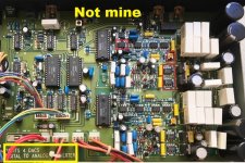
I've looked online and discovered that there is the version like in the schematics I previously attached and there is my Dac, attached photos.
What would be the expected effect (soundwise) adding C304/C404 capacitors?
As some of the opamps are old and maybe with lower performance do you have any suggestions for better opamps? like AD825 for I/U stage or other suggestions?
I also would like to mention that in my Dac1000 there is no AD744 but AD841JN and no 5534 opamps but AD845.
I've looked online and discovered that there is the version like in the schematics I previously attached and there is my Dac, attached photos.
Attachments

I have no op-amp recommendations, but regarding the two capacitors: very small reduction of the treble (something like -0.14 dB at 20 kHz) and far less distortion on high-frequency audio signals.
Sorry to revive this thread but I've just found the correct service manual (it's a Dac-1500 manual but beside the balanced output and the quad pcm63 it's the same).
I'm still trying to figure out how to lower the Parasound's output voltage from 3.1V rms to 2V.
Any suggestions will be appreciated.
I'm still trying to figure out how to lower the Parasound's output voltage from 3.1V rms to 2V.
Any suggestions will be appreciated.
Attachments
It is inside the PCM63. 1K5. Pins 9 and 10. 3K0 across those pins will do the job.Thanks, I'm looking for it but can't find it🙂 can you please direct me?
Thanks
Performance wise which would be the best solution? paralleling 3K0 resistor to pins 9 and 10 or MarcelvdG solution?
Thanks guys
Thanks guys
My version has less impact on the shape of the filter curve than rfbrw's version, but you could use 3 kohm and increase the capacitors C804 from 1 nF to 1.5 nF (with a decent dielectric, such as C0G, polystyrene or polypropylene) for rfbrw's version to correct the response. Besides, my version will have slightly less noise and rfbrw's may have slightly less distortion, but the differences are very small.
If it were up to me, I would just pick the solution that's easiest to fit on the PCB.
If it were up to me, I would just pick the solution that's easiest to fit on the PCB.
Thank you MarcelVdg, I appreciate your comment.
I think I'll try first the easy way🙂 by using the 3k0 resistor.
Btw the C804 capacitor is not installed, it appear in the schematics but is not installed by the factory, I'll put it as you suggested, thanks.
I think I'll try first the easy way🙂 by using the 3k0 resistor.
Btw the C804 capacitor is not installed, it appear in the schematics but is not installed by the factory, I'll put it as you suggested, thanks.
Great!
I wondered if someone might have replaced it with a non-unity-gain-stable op-amp and removed the capacitor for reasons of stability, but that is not the case then. C804 = 1.5 nF with 3 kohm in parallel with it should work fine.
I wondered if someone might have replaced it with a non-unity-gain-stable op-amp and removed the capacitor for reasons of stability, but that is not the case then. C804 = 1.5 nF with 3 kohm in parallel with it should work fine.
- Home
- Source & Line
- Digital Line Level
- Parasound D/AC 1000 output level