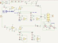
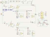
I've built the DSELF PREAMP v13.01and it works wonderful and now I have a smaller chassis that I'd like to fill. I was looking at this old design, it's actually a 4 band parametric. but I only need 2 bands. I did a bread board test and hooked it up to my Wolverine amp, it actually sounds very good, to my ears.
So before I send the Cad drawing to Fabrication, I was hoping someone here can take a look at the schematic to see if I made any blunders or anything else.
Yes Its old school but I have all the parts.
Thanks all.
Scott
So before I send the Cad drawing to Fabrication, I was hoping someone here can take a look at the schematic to see if I made any blunders or anything else.
Yes Its old school but I have all the parts.
Thanks all.
Scott
Attachments
If you only need two bands then why do you prefer parametric instead of a traditional shelving bass-treble solution?
Last edited:
The chassis has holes in it already and did not want to use a 4 band solution.
So I'm guessing there is nothing wrong with the circuit as is?
So I'm guessing there is nothing wrong with the circuit as is?
I've owned a Yamaha C-50 for about 40 years and like how it can add or subtract tones.If you only need two bands then why do you prefer parametric instead of a traditional shelving bass-treble solution?
The thing I'm worried about this design is the input impedance and the balance.
"Rod Elliott - ESP talks about (P-226) the input impedance is determined by R1, which can be up to 100k with a bipolar opamp (e.g. 4558, LM4562, etc.) or 1MΩ if you use a JFET input opamp (e.g. TL072, OPA2134, etc.)."
This has 27k for R1,2. Should these be increased to 1M?
And he also uses a 10k pot for balance in P-02.
Should I change the balance pot to 10k?
I'm not sure.
Your current schematics simulates roughly to this (RV3A and RV9A having mid values):and like how it can add or subtract tones.
A shelving solution would give something like this:
Attachments
Last edited:
There is not much to read actually (googling shelving vs peaking should provide enough links though) , take any amplifier's tone control circuit which has two (bass-treble) tone control buttons and start simulating from there....about shelving circuits?
Center frequencies may vary and the dynamics can be tuned by changing filter component values.
In short - band based equalizers produce "bumps and valleys" in frequency response, shelving tone control produces (usually) continuous flow.
Just for experimenting I once converted a 5 band equalizer to a 5 band set of shelving filters - it worked somehow but in real life turned out to be unuseable.
An example of Marantz PM64 treble control simulations (effect of changing one capacitor value) - I did not like the original sound, it was kind of hollow:

Final...
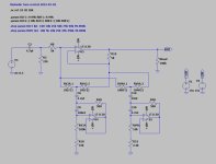
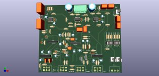
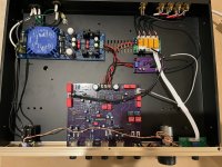
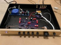
I ended using the bass/treble circuit from the Yamaha C-50. The First stage is from P-266 fig 3 and I set it to about 10dB of gain.
The stage after the tone circuit is from P-88 fig 2 and then to Volume/ bal and final stage from p-88 fig 4.
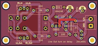
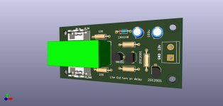
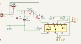
To handle any turn on/off noise, I built a circuit that keeps the Lt/Rt outputs across 100 ohm resistors to ground for about 4 second when unit is turned on.
The Yamaha also used this type of circuit for muting. There is about a +/- 10 dB boost/cut in the range of 100Hz-500Hz and 1kHz-5kHz.
It sounds very good and does not have any noise issues when turning pre-amp on or off. I have it connected to my Wolverine amplifier and it's dead quite to my ears, with the volume all the way down.
Scott
I ended using the bass/treble circuit from the Yamaha C-50. The First stage is from P-266 fig 3 and I set it to about 10dB of gain.
The stage after the tone circuit is from P-88 fig 2 and then to Volume/ bal and final stage from p-88 fig 4.
To handle any turn on/off noise, I built a circuit that keeps the Lt/Rt outputs across 100 ohm resistors to ground for about 4 second when unit is turned on.
The Yamaha also used this type of circuit for muting. There is about a +/- 10 dB boost/cut in the range of 100Hz-500Hz and 1kHz-5kHz.
It sounds very good and does not have any noise issues when turning pre-amp on or off. I have it connected to my Wolverine amplifier and it's dead quite to my ears, with the volume all the way down.
Scott
Attachments
-
 Line out turn on delay.jpg246.1 KB · Views: 83
 -
 Pre-amp Delay mute1.jpg57.6 KB · Views: 76
 -
 Pre-Amp1 cntrl.jpg112.1 KB · Views: 95
 -
Printing Print Schematic.pdf64 KB · Views: 70
-
Printing Print.pdf141.8 KB · Views: 59
-
 Untitled.jpg89 KB · Views: 91
 -
 IMG_0451.jpg238.2 KB · Views: 80
 -
 IMG_0452.jpg300.1 KB · Views: 75
Last edited:

- Home
- Amplifiers
- Solid State
- Parametric tone control Question