Hi,
Im currently undertaking a self led university project to explore the possibility of a portable, battery (pref 9v) powered 3 band parametric EQ to be used by a soundman on location when recording vocal interviews.
Im struggling with adapting the parametric EQ design on this webpage:
Spectrum Analyzer and Equalizer Designs
I have a prototype of the unit built and cant get all aspects of the filter to work together,
I need to know a few things;
1.) Is this design adaptable and if so would it be possible to cascade 3 of these filters.
2.) how do i handle power issues? im of the understanding that a 4.5 volt supply is required for the IC's but i have a feeling im going about this the wrong way which is the source of my issues.
3.) any tips on simulation as im currently using LTspice and having trouble simulating a pink noise test signal.
Any help or any additional pointers would be very much appreciated as i seem to be circling the same issues.
Thanks
All the opamps in these circuits need a split supply i.e. a plus and minus rail with centre ground. The opamp data sheets will tell you the minimum supply.
Don't use a TL074, there are so many better op amps out there. You can get decent op-amps for just a few bucks.
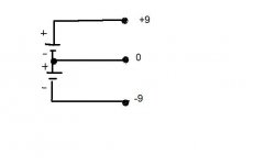
You could use two 9V batteries for your rails to get a +9V and a -9V rail. Check your op amp datasheet for voltage rail options.
You could use two 9V batteries for your rails to get a +9V and a -9V rail. Check your op amp datasheet for voltage rail options.
ok thanks for the tips, 2 batteries is a possibility, another noob question how do i pull a negative voltage from a second 9v cell? prefereably without the use of another IC as uni is closed for the weekend and i was hoping to get this running over the weekend
ok thanks for the tips, 2 batteries is a possibility, another noob question how do i pull a negative voltage from a second 9v cell? prefereably without the use of another IC as uni is closed for the weekend and i was hoping to get this running over the weekend
Think in the "inverse". Merely ground the positive (+) terminal of the 9v battery, and run the negative (-) terminal to your -9 volt rail. No need for any IC's...... this is very straightforward. When you do it, remember that all voltages are "referenced" to your ground..... Your + battery gives you +9 volts, while your - battery will give you -9 volts.
Easy one......
IMHO there is nothing wrong with the quality of the TL074 for your aplication or any audio aplication for that matter.
However, when you have as many as 4 or 5 or more in a circuit they may not fair well on battery power time.
You might want to consider a low power opamp version for your final product.
Below is a data sheet of your average 9v battery.
A TL074 has an average power dissipation of around 200mw and can be as high as 680mw when pushed hard enough.
jer
Attachments
this is all great info thankyou very much, i have my dual battery supply sorted and am not bothered about power consumption at this stage as its only concept proving. im using a minirator and minilyzer to generate a pink noise test signal, i have gain control and cut/boost control but no filter shaping, i think im making a silly mistake when interperating the diagram, the "earths" on the diagram (white arrows) are where my confuson is, do i connect them to the ground (0v) from my batteries or connect it to the non hot line from my minirator?
The white arrows all go to the zero point (0) in diagram in post #6 That point, the 0, is then reffered to as ground and becomes the point from which all voltage and signal measurements are referred to.
You should take alook at this thread where such grounding theme's are discussed in detail. jer
http://www.diyaudio.com/forums/software-tools/185906-op-amp-virtual-ground-spice.html#post2518360
http://www.diyaudio.com/forums/software-tools/185906-op-amp-virtual-ground-spice.html#post2518360
"jer is right. The TLO7x/08x are great. I allways liked the built-in white noise generator. E "
I was not stating that they are the best opamp available ,but quite adequate for audio aplications.
And they are 1000 times better than the LM324 that I used when I started learning about opamp circuits. jer
I was not stating that they are the best opamp available ,but quite adequate for audio aplications.
And they are 1000 times better than the LM324 that I used when I started learning about opamp circuits. jer
IMHO there is nothing wrong with the quality of the TL074 for your aplication or any audio aplication for that matter.
Actually yes, I take it back - the TL074 isn't bad at all for audio.
- Status
- Not open for further replies.
- Home
- Design & Build
- Construction Tips
- Parametric EQ project