Thanks for the reminder, I do intend to have a voltage divider at output to float the heater, which I intend to double as a resistor bleeder. That said, the value I selected is 360k+120k ohms (2W, 750V limit each) which would drain the resistor over a longer period than the value what you recommended. I did not put this in the simulation because of software limitation.
In general, how much bleed current is a reasonable value?
The software only allows resistive load to be added at the very end, not at the beginning, not in the middle.
It allows constant current load in the middle and the end, not at the beginning
After the rectifier, it only allows C, LC, or RC stage.
I think I figured out where the problem lies.
When I remove the stepped current load, as in the load current is a constant 70mA x 2 right from 0 sec. The PIV does not get beyond 1300V.
So in my earlier simulation with the load current at 2x1mA at 0 sec, the first choke is below the critical H value. So the large capacitor after the choke becomes the input capacitor, and the circuit behaves like a C input. And that C value is way above the 60uF specified in the 5AR4 datasheet.
Now the question becomes, if this warning can be ignored considering 5AR4 will not be conducting before it warms up, neither are the tubes it powers. Earlier I started a thread on this and the answer seems to be that this should be fine in practice?
Last edited:
1. Depending on the output tubes, the 5AR4 might be conducting before the output tubes do.
For an amplifier that uses Directly Heated output Tubes (45, 2A3, 300B, that are powered by a non delayed AC filament supply) the output tubes will conduct before the 5AR4 rectifier.
But . . .
Most of the complex DC filament supplies that power 45, 2A3, 300B will delay the warmup of those output tubes. So the 5AR4 may conduct first.
For Indirectly heated output tubes, KT88, EL34, etc., the 5AR4 may be conducting long before the output tubes are.
For all of the above, Your Mileage May Vary.
2. You have approximately the following (if you use a 50k Bleeder resistance):
A 350VDC supply with 500uF total capacitance, and 50k bleeder resistor.
The RC time constant of 500uF and 50k Ohms is 25 seconds.
Start with 350V, then turn power off
25 seconds later you have 127V
After 50 seconds, you have 46V
If it takes you 60 seconds to get the bottom cover off of the amplifier, you are relatively safe.
(After 60 seconds, at least it meets the 42V maximum exposed voltage of test equipment).
350V / 50k = 7mA when the amp is on.
No, your divider for floating filaments does not draw enough current to ‘double’ as a good bleeder.
Always wash your hands (for the virus).
But . . .
NEVER wash your hands just before working on vacuum tube amplifiers.
Safety First!
Whether you use a choke input filter, or a small capacitance input filter, connect the 50k bleeder from the rectifier cathode, and the other end to ground (B+ return).
But since the software does not like that, put it across the last capacitor when you enter the simulation schematic values.
Be careful, all the series resistors from filter cap to filter cap should have wattage ratings 5 X the power they will dissipate. If a short occurs, they should survive, and the bleeder resistor(s) will bring the capacitors to a safe voltage before you open the bottom cover to investigate.
Last edited:
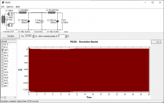
The software won't do what you are asking. This is the best I can do. Yes the wild rectifier voltage is gone. Even if I use 240k ohm value (my current configuration, 2 strings of 360k + 120k ohms), it has the same effect.
So I can do with or without the capacitor.
I have learned that one should always assume any capacitor in an amp as charged, discharge and measure before any work. I have a 100W light bulb (max 250V) just for this, then followed with resistors.
Also bought a pair of 12kV rubber glove for poking around a live amp. Feet off ground and one hand behind back. I would like to live long enough to hear how my amp sounds like.
Attachments
I have some high voltage gloves.
They reduce my manual dexterity.
Also, some parts of an amplifier may have a wire end through a solder lug, and pointing out, or up. I might not see one and cut it off.
It could easily poke a hole through most gloves.
I hate working on a powered amplifier with it upside down.
Have to prop it up with books to keep it from crushing the tubes.
Some smart people use a kind of clamp/vice with wood ends to hold the upside down amp.
I drill holes in the chassis top or sides and mount test points, and plug the meter leads in.
Or, I use tube extenders and probe them with the DMM.
That is all my personal methods and preferences.
The method you choose is not important, only how well and how carefully you execute them.