Please pardon this very basic question, I've been out of this for a while and I'm quite rusty.
This is for an unregulated PSU. If I parallel LC filters like this to improve channel separation, does it count as paralleling inductors where the resulting inductance is reduced?
This is for an unregulated PSU. If I parallel LC filters like this to improve channel separation, does it count as paralleling inductors where the resulting inductance is reduced?
Attachments

Last edited:
Might as well ask this on the same thread.
I tried to use PSUD2 to simulate, but it does not allow branching off the PSU like this, so I did the best it could. I wonder if there is a possibility that the 2 parallel LC filters would ring with each other? I have not drilled my chassis so it's a good time to back off.
I tried to use PSUD2 to simulate, but it does not allow branching off the PSU like this, so I did the best it could. I wonder if there is a possibility that the 2 parallel LC filters would ring with each other? I have not drilled my chassis so it's a good time to back off.
Attachments
Last edited:
1 / (2 x pi x (root (454nf x 5H))) = 105.6 Hz
454nF and 5 Henry resonate at 105.6 Hz.
Full wave rectification of 50 Hz = 100 Hz.
The filter is too close to resonance.
Full wave rectification of 60 Hz = 120 Hz.
The filter may be too close to resonance.
Your mileage may vary.
I would not use that combination in my amplifiers power supply.
The input may ring. Software may, or may not, overlook that.
The output will not ring.
Change the 5H, or change the 454nF.
A 50% change in one or the other only changes the resonance by 35%.
Recalculate resonance with the new value(s).
If you change the capacitor, the problem is you get a different B+ voltage (and a different ripple voltage at the output).
If you change the inductor, you get a different ripple voltage, but the B+ voltage remains the same (except for different DCR drop).
Complete.
I do not use power supply software. I design by longhand, and then I check my work with actual measurements.
To each his own method.
Last edited:
Oopsie, it's a "mistake", the first choke is actually 4H, I used 5H because it appears to be harder to stabilise. Which works out to be 118 Hz, is it still too close?
Last edited:
4 Henry is about 2500 Ohms at 100 Hz.
100 milli Ohms ESR is in series with choke DCR (40 Ohms?).
The Q is 2500 Ohms / 40.1 Ohms.
Q = 62.3
118 Hz is perhaps a little to close to 100 Hz.
The capacitance you measured, but the inductance you measured varies depending on the load current.
If you change the inductor to 2.5 Henry, the resonance moves to 149 Hz.
But then the ripple voltage will double.
So . . . double the capacitance of the 2nd capacitor in the filter, and the ripple will be the same as it was with the 4 (or 5) Henry choke.
And, add a resistor in series with the 2.5 Henry choke to make the total be 40 Ohms, just as it was with the 4 or 5 Henry choke. That will give the same B+ voltage out.
Just one caution, the rectifier may not like the inrush current of the 2nd capacitor, but the 2.5 Henry 1571 Ohm inductive reactance will most certainly make it OK for a good quality 5AR4 rectifier.
5AR4 is rated at 750mA maximum peak.
450V x 1.414 = 636V peak.
636V peak / 0.75 Amps peak = 848 Ohms
But the 2.5 Henry inductive reactance at 100 Hz is 1571 Ohms, so you are OK.
Last edited:
I can change the input cap to 1uF or so with minimal change in output voltage. The resonance frequency would then be 79Hz.
That would still be too close I guess.
How about I increase it further and push it to 70Hz? Do I have to avoid 50-60Hz region as well?
That would still be too close I guess.
How about I increase it further and push it to 70Hz? Do I have to avoid 50-60Hz region as well?
I ended up halving the input cap to 200n, so 178Hz. Minimal output voltage change. Actually I was planning for a choke input supply, but PSUD2 keeps throwing up warning. Adding a tiny cap in front solved the issue. It wasn't meant to increase voltage output.
The requirement for a true choke input power supply is:
No input cap
And . . .
The choke must have at least the Critical Inductance.
Critical Inductance for 60 Hz mains (with 120 Hz full wave rectification):
350 / Load in mA.
for example, 50mA load: 350 / 50 = 7 Henry (use a 10 Henry choke).
If you did not have at least critical inductance when you had no input cap,
That might have made the Software not work.
The software assumed you were trying to use true choke input filtering, but did not use at least the critical inductance value.
So it put up the warning?
Or, the Software does not know how to deal with choke input at all, even if you did use at least critical inductance.
With solid state rectifiers (minimum voltage drop) and center tapped full wave rectification, the maximum voltage out of a choke input power supply is 0.9 x 1/2 winding rms voltage. There will be additional voltage drops due to the power transformer primary DCR, secondary 1/2 winding DCR, and choke DCR.
With 50 Hz mains (and using full wave rectification 100 Hz)
The critical inductance is (350 x (120 / 100)) / Load mA.
That is 420 / Load mA.
For 50 mA load, the critical inductance is 420 / 50 = 8.4 Henry, use 10 Henry.
(it was minimum 7 Henry for 120 Hz full wave).
Note: For 50 Hz mains, and full wave rectification (100Hz), the only 50 Hz that "gets to" the filter is if the alternations are unbalanced (unbalanced 1/2 winding versus the other 1/2 winding, or one plate dropping more voltage than the other plate - you probably will not have to worry about either of these).
But 79 Hz does seem like it is still to close to 100 Hz (at least for me).
Last edited:
First of all, I have to mention that I really appreciate your inputs, it is the reason why folks like me with no electronics background can even be in this hobby.
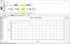
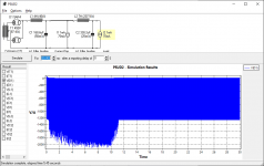
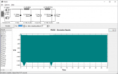
In the first graph, it is the current through the rectifier with the input capacitor.
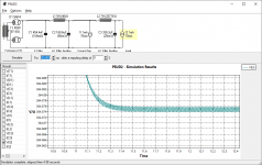
In the second graph, it is the current through the rectifier without the input capacitor.
The third picture is the warning message I get without the input capacitor. My guess is in practice this can be ignored as the software don't seem to take into consideration the slow turn on of 5AR4.
Of course, for folks like us who relies on software like this and don't know how to do the actual calculation, can't claim to know what the software can or cannot do. I started using this software as it is highly recommended by people here, my guess is it can handle choke input or cap input and anything in between. It is not perfect though.
In the first graph, it is the current through the rectifier with the input capacitor.
In the second graph, it is the current through the rectifier without the input capacitor.
The third picture is the warning message I get without the input capacitor. My guess is in practice this can be ignored as the software don't seem to take into consideration the slow turn on of 5AR4.
Of course, for folks like us who relies on software like this and don't know how to do the actual calculation, can't claim to know what the software can or cannot do. I started using this software as it is highly recommended by people here, my guess is it can handle choke input or cap input and anything in between. It is not perfect though.
Attachments

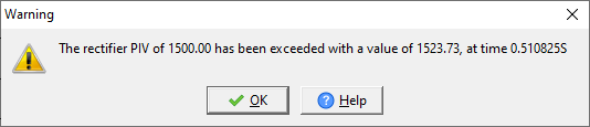
You exceeded the Peak Inverse volts for the 5AR4.
The 5AR4 maximum Peak Inverse volts is 1500.
I can see from the current and voltage spikes at the beginning, that the amplifier load does not come on, so B+ is unloaded. After 10 seconds you see the current and voltage come up, because the load (tubes) are warm, and draw current). Good Software assumptions.
But, the 454.4 nF and 5 Henry are a parallel resonator at the 5AR4 cathode.
A parallel resonator there increases the voltage to more than 450 x 1.414 = 636.4V peak.
There is a small voltage drop in the rectifier (perhaps 30 or 40V, there is no load yet from the output tubes).
With a cap input filter, and 450V x 1.414 = 636.4V
When one rectifier plate is off, the peak inverses volts is 636.4V plus 636.4V from the first capacitor that is charged (minus the 30 to 40V rectifier drop).
But the 454nF and 5 Henry resonate, and make the voltage far more than 636.4V.
That explains the software warning.
Re-run the software with 454nF and 2.5 Henry, and see if the message goes away.
Now I am starting to trust the software a little more.
Peak Inverse volts happens when One plate is at the negative peak voltage of the transformer (like 450 x 1.414 = -636.4V peak); but at the same time, the other plate is at the positive peak, +636.4V. The 636.4V (minus the 30V or 40V rectifier drop) is applied to the first capacitor).
So the first plate sees - 636V, but the cathode is at +630V, so the peak inverse voltage is 636 + 630V = 1266V.
But in your case the resonance of the first cap and the inductor raises the 630V to a very much higher voltage.
1523.73V - 636V = 887.7V. The resonator is increasing the peak volts at the cathode to 887.7 Volts!
This can be harmful to the rectifier, and if the capacitor can not take 887.7 Volts it is harmful to the capacitor too.
Last edited:
Btw, the warning on PIV comes only when there is no input capacitor.
But your calculation is spot on on the input cap voltage, the simulation shows it can reach 900+V. My cap is rated at 2kV, but I am concerned about the rectifier's life.
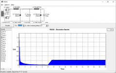
Thanks to you, I now know where to look. The graphs below show the voltage that the rectifier sees with no cap, 200nF cap, and 2uF cap. I believe this is where the warning is from.
My total load current would be about 120-160mA depending on tube and bias, so the minimum critical inductance for 100Hz would be between 2.2-2.9H I guess.
The 200nF configuration will probably work fine. I already have the 4H choke. I can get a 3H choke. 2.5H I would have to look.
With no input cap, I cannot get the PIV under control. I suspect you have an explanation for this.
I also assume I do not have to add resistor on the transformer secondary as specified in the 5AR4 datasheet, since the cap size is rather negligible?
But your calculation is spot on on the input cap voltage, the simulation shows it can reach 900+V. My cap is rated at 2kV, but I am concerned about the rectifier's life.
Thanks to you, I now know where to look. The graphs below show the voltage that the rectifier sees with no cap, 200nF cap, and 2uF cap. I believe this is where the warning is from.
My total load current would be about 120-160mA depending on tube and bias, so the minimum critical inductance for 100Hz would be between 2.2-2.9H I guess.
The 200nF configuration will probably work fine. I already have the 4H choke. I can get a 3H choke. 2.5H I would have to look.
With no input cap, I cannot get the PIV under control. I suspect you have an explanation for this.
I also assume I do not have to add resistor on the transformer secondary as specified in the 5AR4 datasheet, since the cap size is rather negligible?
Attachments

Also, in the simulation I set the current draw to be 1mA in the beginning, then ramp up to 70mA after 10 seconds. This is done to to trigger ringing at the output, it is sort of a trick workaround for PSUD2 to overcome the limited functionality.
One thing that occurs to me is that you forgot to use a bleeder resistor.
Safety First!
Prevent the "Surviving Spouse Syndrome".
The capacitors will hold a charge for a long time.
Often the amplifier tubes do not completely discharge the caps at power-down.
Then you get your fingers in there, and Ouch is the best that can happen.
A pair of 25k 25 Watt resistors in series (50k total) makes a great bleeder for up to 700VDC B+.
Because of the trouble you are having, I would connect one end of the bleeder series resistors from the junction of the rectifier and the choke. Connect the other end of the bleeder series resistors to ground (B+ return).
1. Put those bleeder resistors there instead of the input capacitor.
Run the Software again.
2. Put those bleeder resistors there, and the input capacitor too.
Run the Software again.
Last edited:
- Home
- Amplifiers
- Tubes / Valves
- Paralleling LC filter