Conrad Hoffman said:.... The numbers for PSRR have to be stretched to the breaking point to consider power supply caps part of the signal chain...
...yupp that's exactly why I am wondering when somebody tells me that the supply cap has a major influence on bass control. At these frequencies the PSSR of any normal power amp is 60db or higher (except class D !!!) .
And in fact I never observed any dominant low frequency artifacts of the rails in my output voltages.
May be we have to dig deeper. If there is a real corelation between supply caps and bass response, then it is not a very obvios one. The obvious straight forward effects are no issue IMHO. At least up to now all my measurements indicate close to perfect behavior in this regard. If all this is not a myth, then there must be a less obvios effect. I know that different bass sound & control is not a myth, even if you only change the amp and keep everything else the some. But I do not know if and how this is really caused by the rail caps.
Hm... may be we should open another thread for this.. or add our thoughts to an existing rail-cap-bass-thread...
ChocoHolic said:
...yupp that's exactly why I am wondering when somebody tells me that the supply cap has a major influence on bass control. At these frequencies the PSSR of any normal power amp is 60db or higher (except class D !!!).
The Hypex gang might have something to say about that: according to their spec sheet, PSRR on UcD400s is better than 65 dB on all frequencies.
From the Cornell Dubilier application guide
Self-resonance is typically below 100 kHz depending on
capacitance. At self-resonance the device is resistive and
beyond it is inductive.
Dissipation factor is the measurement of the tangent of the
loss angle (tan ) expressed as a percentage.
ESR declines steadily with increasing frequency and cross-
es over to constant ESR at a frequency inversely propor-
tional to capacitance. This crossover is typically below 10
kHz. The ESR of high-capacitance capacitors changes little
with increasing frequency because high-capacitance causes
them to have low crossover frequencies. The ESRhf ranges
from 0.002 for large, screw-terminal capacitors to 10
for miniature devices.
ChocoHolic said:
...yupp that's exactly why I am wondering when somebody tells me that the supply cap has a major influence on bass control. At these frequencies the PSSR of any normal power amp is 60db or higher (except class D !!!) .
And in fact I never observed any dominant low frequency artifacts of the rails in my output voltages.
May be we have to dig deeper. If there is a real corelation between supply caps and bass response, then it is not a very obvios one. The obvious straight forward effects are no issue IMHO. At least up to now all my measurements indicate close to perfect behavior in this regard. If all this is not a myth, then there must be a less obvios effect. I know that different bass sound & control is not a myth, even if you only change the amp and keep everything else the some. But I do not know if and how this is really caused by the rail caps.
Hm... may be we should open another thread for this.. or add our thoughts to an existing rail-cap-bass-thread...
I agree, but there is no correlation, this is just another myth. Only bass clipping behaviour depends on how much capacitance is employed.
I found some something that looks GREAT:
http://www.cde.com/applets/CDEspiceApplet/aframe.htm
I am just now getting ready to try this applet. But it looks like EXACTLY what is needed, for modeling frequency-dependent electrolytic capacitor effects in Spice.
And I quote (from the URL above):
"Cornell Dubilier now offers Spice models of many of its wet aluminum electrolytic capacitors. We have a new online impedance modeling applet that allows the user to select any standard catalog part number among 16 types. The capacitance, ESR, and impedance are then graphed versus frequency at several temperatures. A Spice simulation program listing is available with a mere click of a button, and this model is readily cut and pasted into a Spice simulator. This is a new offering from Cornell Dubilier, and we will be refining the models and adding new types over the coming months."
Hallelujah!
- Tom Gootee
http://www.fullnet.com/~tomg/index.html
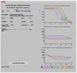
Attached is a screen-shot of the Cornell Dubilier Impedance Modeler applet. (I had to use Alt-PrtSc to get it to copy the screen to the clipboard, in Internet Explorer.)
I had rested my mouse point on the -40degC curve, at 10 kHz, in the top plot, which brought up the capacitance value under those conditions, seen in the little pop-up box on the plot.
I had rested my mouse point on the -40degC curve, at 10 kHz, in the top plot, which brought up the capacitance value under those conditions, seen in the little pop-up box on the plot.
Attachments
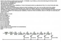
And here is the SPICE model that it generated, for the example capacitor I had selected (12000uF, 25v, 401C series):
CDE Spice Applet for Electrolytic Capacitors, Rev 07-28-03
* INPUTS:
* Part Number: 401C123U025AK8
* Type: 401C
* 3-pin Plug-in Capacitors
* Widest Temperature Range, -55 to +105 ºC
* Diameter: 1.375
* Length: 1.625
* Typical ESR (120 Hz, 25 ºC): 28.7
* 65 ºC DC Capacitance: 10982.4 uF
* Series Inductance: 22.5 nH
* 65 ºC Metal Resistance: 0.0024 ohms
* 65 ºC Spacer-Elyte Resistance: 0.0191 ohms
* 65 ºC Tunnel Resistance: 0.0028 ohms
* 65 ºC Spacer Resistance: 0.0163 ohms
**************************** CORNELL DUBILIER WET ALUMINUM ELECTROLYTIC CAPACITOR SPICE MODEL:
.SUBCKT CDE_WetAluminumElectrolyticCapacitorMIL 1 10 PARAMS: Cnom=10982.4u Ls=22.5n Rm=0.0024 Rspp=0.0163 Rtun=0.0028
* VALID FOR AC, DC, TRANSIENT SPICE ANALYSIS
* MIL ELECTROLYTE PARAMETERS
* BE SURE TO SET TNOM=65 ºC
* VALID FOR RANGE 45-85 ºC ONLY (GENERALLY THIS IS THE RANGE IN WHICH ALUMINUM ELECTROLYTIC CAPACITORS ARE USED)
* SKIN EFFECT IS NOT MODELED
* DIELECTRIC LOSS IS NOT MODELED (BUT DOES NOT AFFECT EXTERNAL CICUIT, ONLY CALCULATED CAPACITOR LOSSES)
* ZENER CLAMPING EFFECT IS NOT MODELED (BUT ONLY AFFECTS EXTERNAL CIRCUIT IF VOLTAGE RATING IS EXCEEDED)
* REVERSE VOLTAGE CLAMPING EFFECT IS NOT MODELED (BUT ONLY AFFECTS EXTERNAL CIRCUIT IF REVERSE VOLTAGE IS APPLIED)
* DC LEAKAGE CURRENT IS NOT MODELED (BUT GENERALLY DOES NOT AFFECT EXTERNAL CIRCUIT IF APPLIED VOLTAGE IS BELOW RATED VOLTAGE)
Lseries 1 2 {Ls}
Rmetal 2 3 {Rm} TC1=0.0039
Rsp 3 4 RT {Rspp}
R1 4 5 RT {0.658*Rtun}
R2 5 6 RT {0.1*Rtun}
R3 6 7 RT {0.05*Rtun}
R4 7 8 RT {0.2*Rtun}
R5 8 9 RT {0.3*Rtun}
C1 5 10 CT {Cnom/32}
C2 6 10 CT {Cnom/16}
C3 7 10 CT {Cnom/8}
C4 8 10 CT {Cnom/4}
C5 9 10 CT {Cnom*0.532}
.MODEL RT RES TC1=-0.00404618508 TC2=0.0000295452624
.MODEL CT CAP TC1=0.001
.ENDS
***************************
gootee said:Attached is a screen-shot of the Cornell Dubilier Impedance Modeler applet. (I had to use Alt-PrtSc to get it to copy the screen to the clipboard, in Internet Explorer.)
I had rested my mouse point on the -40degC curve, at 10 kHz, in the top plot, which brought up the capacitance value under those conditions, seen in the little pop-up box on the plot.
Take care with setting the Ls to zero. It is indicating the impossible. In fact if you look to the low impedances of a several k uF then already 5-10nH will start to dominate the impedance somewhere between 10kHz and 100kHz. And as long as we are not able to transfer the geometrie of such large caps into the hyperspace you should consider at least 5-10nH, - even is your PCB is perfect.
gootee said:Attached is a screen-shot of the Cornell Dubilier Impedance Modeler applet. (I had to use Alt-PrtSc to get it to copy the screen to the clipboard, in Internet Explorer.)
I had rested my mouse point on the -40degC curve, at 10 kHz, in the top plot, which brought up the capacitance value under those conditions, seen in the little pop-up box on the plot.
Capacitance seems to vary enormously with cap temperature.
Can it really fall by about 50% when the caps are at room temperature cf, 80degC?
Would that explain some of the claims regarding SQ changes as the amplifier warms up?
[First, a little recapping:]
Cornell Dubilier now has this great Java capacitor-modeling applet on-line:
----------------------------------------------------
http://www.cde.com/applets/CDEspiceApplet/aframe.htm
----------------------------------------------------
This free, on-line Java applet plots capacitance, ESR, and impedance, versus frequency, at several temperatures, for many of Cornell Dubilier's wet electrolytic capacitors (more series are being added, apparently), AND, with a mouse-click, AUTOMATICALLY GENERATES A TEMPERATURE- AND FREQUENCY-DEPENDENT SPICE MODEL for any particular capacitor that's been included by CDE.
These automatically-generated temperature-and-frequency-dependent electrolytic capacitor models work well in AC, DC, and transient analysis modes, in LTspice.
(Aside: Note that whenever I click on the "Impedance Modeler" link at the above CDE link, I always get "Object Not Found", at the top. But everything still works, if you wait for the applet to appear.)
-------------------------
[Now, a little new stuff, about using the models in LT-Spice:]
It appears that they always use the same schematic, for the capacitor model, which I derived from their netlists and posted in an earlier message, in this thread.
With LTspice, at least, you can also create a new re-usable "F-capacitor" symbol (with + lead as node 1 and - lead as node 2, in the .asy symbol file), insert it into a schematic, and then right-click on it and copy and paste the SUBCKT name from the CDE-applet-generated subckt text file into the VALUE field,
e.g. "CDE_WetAluminumElectrolyticCapacitorLV",
and cut and paste the PARAMS portion into the VALUE2 field,
e.g. "PARAMS: Cnom=4301.4u Ls=14.0n Rm=0.0048 Rspp=0.0368 Rtun=0.0055".
If you save the CDE-generated subckt model text file, with the entire PARAMS portion removed from the .SUBCKT line, and then use a .include Spice Directive (.op button) to include it in your schematic, you can then use multiple instances of your new F-capacitor symbol, for different capacitor values and types, just by right-clicking on the cap's symbol and putting the correct subckt name in the VALUE field and the applet-generated PARAM: statement in the VALUE2 field.
To be more clear: You should only need to save ONE copy of the generated spice model text subckt file, as long as you remove the PARAMS: portion of the SUBCKT line (i.e. Remove "PARAMS:" and everything after it, in the .SUBCKT line in the CDE-generated spice model text file, and then save the file with whatever name you want to use in the .include directive in your schematics. Apparently you can also change the actual .SUBCKT name to something shorter or more convenient, as well.)
Cautionary Note/Warning: For now, it APPEARS that the same schematic is used for all of the generated models for all of the CDE capacitor series/types. And although the SUBCKT names are different for some of the generated models, it appears that the only significant differences between any of the generated model files are in the PARAM: statement. However, I have not checked EVERY one of their capacitor types' models. And, even if they are all the same, for now, that may change, in the future. So users should be vigilant about making sure that any generated models do match the single saved SUBCKT text file, if they want to use this re-usable symbol method. (If CDE does later change the model, e.g. different models for different capacitor types or series, you might need to save one subckt text file for each .SUBCKT name they use.)
Also, make sure to read the notes in the generated model file about setting the TNOM temperature parameter. (See below.)
P.S. :
I forgot to mention that it might be a good idea to check the "Visible" box for the VALUE2 line that contains the PARAMS:
statement.
Also, in the CDE-generated model file, they mention setting a "TNOM" temperature parameter. I think that, for LTspice, it's simply the TEMP parameter. Stepping TEMP, with a spice directive such as ".step TEMP 50 100 25", or ".step TEMP list 50 75 100", does change the frequency response of the capacitor model, versus TEMP. (And setting a "TNOM" parameter apparently has no effect, unless I'm doing it in the wrong place or something.)
As an example, you can connect a simple current source across the capacitor, and right-click on it and set its AC value to 1. After plotting the voltage at the cap's + terminal with an AC Analysis spice run, you can right-click on the voltage's plot heading and change the expression to be the voltage divided by the current source's current, e.g. V(n001)/I(I1). Then you can left-click on the vertical scale and change it to "Linear", to see the impedance plotted in Ohms, versus frequency (with Omega symbols in the vertical scale values, at least if nothing else is plotted). Adding a ".step TEMP [low] [high] [increment]" or a ".step TEMP list temp1 temp2 ... tempn" spice directive should then give an impedance versus frequency plot for each temperature.
Enjoy!
Regards,
Tom Gootee
http://www.fullnet.com/~tomg/index.html
This thread is very long, thus I didn't read it all.
It is my understanding that the film caps in parallel with the electrolytics is to dampen the supply rails. Under certain conditions of improper values and other things like Q they can make things worse.
A film cap with a small ceramic is probably the best, IMHO.
Undesirable transients in audio are to be minimized. Under certain conditions the rails may oscillate for a brief moment. The small caps dampen this tendency.
I will also add that tantalums are undesirable because the failure mode of a tantalum is a dead short whereas the failure mode of an aluminum electrolytic is an open circuit.
As for the issue of electrolytics affecting bass response. I would say the issue here is ESR. When the amp needs a surge of current the caps have to let go with it ASAP.
Low ESR caps will give much better bass resonse. I say this because I tested electrolytics for filtering hum. A low ESR cap of half the value of a standard electrolytic will do as much hum filtering as the standard electrolytic.
Low ESR caps are expensive, but they are probably worth more in an audio sense than a large bank of standard ones. IMHO, Mark
hailteflon said:This thread is very long, thus I didn't read it all.
It is my understanding that the film caps in parallel with the electrolytics is to dampen the supply rails. Under certain conditions of improper values and other things like Q they can make things worse.
A film cap with a small ceramic is probably the best, IMHO.
Undesirable transients in audio are to be minimized. Under certain conditions the rails may oscillate for a brief moment. The small caps dampen this tendency.
I will also add that tantalums are undesirable because the failure mode of a tantalum is a dead short whereas the failure mode of an aluminum electrolytic is an open circuit.
As for the issue of electrolytics affecting bass response. I would say the issue here is ESR. When the amp needs a surge of current the caps have to let go with it ASAP.
Low ESR caps will give much better bass resonse. I say this because I tested electrolytics for filtering hum. A low ESR cap of half the value of a standard electrolytic will do as much hum filtering as the standard electrolytic.
Low ESR caps are expensive, but they are probably worth more in an audio sense than a large bank of standard ones. IMHO, Mark
Of course you have not read through the thread. All the content of your post is wrong, you are repeating the classic myths.
Electrolytics used alone are resistive and damped at RF, but the system becomes resonant and not damped when smaller value films or ceramics are paralleled. Paralleling medium value films and low value ceramics causes several resonant peaks. Paralleling should be done with great care.
ESR is completely meaningless at bass frequencies because capacitive reactance (the impedance component coming from capacitance and frequency) dominates.
Consider reading the thread, you may learn something (better than popular wisdom) about capacitors.
Eva said:Electrolytics used alone are resistive and damped at RF.....
That's a bit confusingly phrased. Anything with physical length has an inductance, so cap + trace has some value of L to consider at some high frequency, even 'perfect' caps.
Mark, I'm sorry, but I have to agree with EVA. Please read the whole thread and also follow the links given. Your incorrect statements, like "Under certain conditions the rails may oscillate for a brief moment. The small caps dampen this tendency", give rise to the assumption that you will benefit a lot from that.
- Klaus
- Klaus
KSTR said:Your incorrect statements, like "Under certain conditions the rails may oscillate for a brief moment. The small caps dampen this tendency", give rise to the assumption that you will benefit a lot from that.
- Klaus
Well, he is partially right, or at least on the right track. Contrary to some assertions made here, most electrolytic capacitors make quite lousy supply rail bypasses as RF (and here they are NOT merely resistive
 )
)Nearly anything over 100uF falls in a heap above a few tens of MHz, and degrade significantly quite a lot earlier.
I do a lot of mixed signal RF / audio stuff where stages are decoupled from each other with RC, LC (or combination) filtering of the supply rails, where it is necessary to decouple the rails for both audio frequencies and RF frequencies. A small 100nF MKT capacitor (for example) in parallel with a typical 100uF electrolytic can easily give a 20dB or more reduction in the impedance bypassing the rail to ground at 50MHz.
To provide adequate bypassing from near DC to HF, VHF or beyond it is generally necessary to parallel up a range of values – say 100uF, 1uF, 100n, 1n…… etc.
Parallel resonances generally are not much of a problem (or less of a problem than avoiding further RF bypassing) because of the typical lousy Q’s of the inductances.
Anyone with access to some pretty rudimentary equipment can check for this themselves. Make an RC low pass filter with, say a 100-ohm resistor and a 100uF electrolytic and connect to a signal generator (turn the DC offset knob up to polarise the cap if desired). Crank the sig gen up to 50MHz and observe the output of the LPF on an oscilloscope. Connect a 100nF cap in parallel with the 100uF and you’d likely see the output drop 20dB or so. Run a hand-cranked frequency sweep and watch the CRO for parallel resonant frequency peaks if you want. I've done heaps of this stuff. Bypassing RF is nearly always a PITA.
Now all this might seem irrelevant to audio, but that is not necessarily so – especially if you are building, say, a pre amp, with several rather high GBWP opamps, which require adequate supply rail bypassing out to tens of MHz, for example.
Of course you can get 20dB lower impedance at 50Mhz (or at 500Mhz for that mather) but it is at the expense of 20dB higher impedance around 5Mhz... This is not an advantageous trade for audio because most amplifiers have its unity gain around this frequency and rail resonance will degrade phase margin. Every added capacitor produces a resonant peak. Measuring impedance at a single frequency tells very little information.
Note that I'm making my best effort to believe you because I have *never* ever seen dissimilar capacitors paralleled locally and directly in all the RF circuits (like TV and radio tuners) that I have ever tried to reverse engineer, though, with the only exception of a small high-ESR low-value electrolytic paralleled with a ceramic (this is known to be non-resonant). Mostly I have only seen LC and RC filters in RF circuits. Two or more dissimilar capacitors placed together and connected in parallel are only routinely seen in exotic audio equipment.
On the other hand, only in certain applications where you know that you will be drawing current from the supply only above 50Mhz and below 20Khz you can afford a resonant peak in the middle.
In other applications like SMPS you will hardly see paralleled capacitors, despite the low supply impedance requirements, because it's quite easy for switching harmonics to trigger inter-capacitor resonances and end up with 20dB higher electromagnetic interference figures... Instead, LC filters are used to smooth the voltage ripple that results from electrolytic capacitor impedance, and this is a much more effective solution because you have full control over the resulting resonant peak (paralleled capacitors resonate at *unpredictable* frequencies that depend too much on layout and capacitor batches). The resistive nature of electrolytics at RF actually helps to prevent EMI by damping resonances that would otherwise hapen with an ideal purely capacitive supply interacting with PCB track inductances and power transistor/diode capacitances (and lead inductances).
- Status
- This old topic is closed. If you want to reopen this topic, contact a moderator using the "Report Post" button.
- Home
- Amplifiers
- Power Supplies
- paralleling film caps with electrolytic caps