Hey Oliver,
Currently trying to smush "Advanced Electrodynamics" into my head for my degree. Maybe after the exam season, eh?
Chris
Currently trying to smush "Advanced Electrodynamics" into my head for my degree. Maybe after the exam season, eh?
Chris
I cannot find the discussion Brian referenced in Post #13.
Now you have me intrigued. I'll do a dig and see if I can pull up the reference.
This is all good stuff and confirms why I am using series 6th order bandpass to provide wide bandwidth, cone motion control, and reduction in harmonic distortion of the driver for my XKi design.
http://www.diyaudio.com/forums/full-range/268524-xki-xs-ab-initio-karlson-6th-order-bandpass.html
A 6th order series tuned bandpass script in akabak is very simple - it could literally be done in 8 or 10 lines of code. I will post when I get a chance.
The tuning freq overall is definitely linked together - it is a coupled system by definition.
I am seeing very low harmonic distortion over a wide range as cone motion is so small. Will post data when I get everything together.
Could you please post the Akabak script?
I'm finally feeling motivated to learn to use Akabak. I'd really like to understand what going on here, hopefully Akabak can help me do that.
Hi X,
Thanks. You make that look too easy. 🙂
Regards,
Sure thing. 🙂
There are instructions and a script for the little RS100P-4 driver XKi here:
http://www.diyaudio.com/forums/full-range/268524-xki-xs-ab-initio-karlson-6th-order-bandpass-16.html#post4208625
Sure thing. 🙂
There are instructions and a script for the little RS100P-4 driver XKi here:
http://www.diyaudio.com/forums/full-range/268524-xki-xs-ab-initio-karlson-6th-order-bandpass-16.html#post4208625
Thanks! Your example was enough for me to get a working test for comparing a parallel BP6 to a series BP6 in Akabak.
Found some interesting stuff, here is the comparison between the styles. They both have equal chamber volumes and tunings:

The top is the series tuned and the bottom is the parallel tuned.
Found some interesting stuff in regards to port tunings as well. If everything is left the same (port dimensions) and you convert a parallel tuned box to series tuned the rear port tuning goes down, which makes sense, but the front port tuning goes up. Trying to modify the port lengths to bring those two port tunings closer together where I want them to be doesn't work out real well either.
Jessman,
Great that you tried it and now experimenting. That's what it's great for - asking what if?
There are basic rules of thumb on high SPL designs: rear chamber equals double front chamber etc.
Great that you tried it and now experimenting. That's what it's great for - asking what if?
There are basic rules of thumb on high SPL designs: rear chamber equals double front chamber etc.
Jessman,
Great that you tried it and now experimenting. That's what it's great for - asking what if?
There are basic rules of thumb on high SPL designs: rear chamber equals double front chamber etc.
So I have discovered a few things so far:
1. First off I got my original question answered, series-tuned BP6 enclosures do NOT perform the same as a parallel-tuned BP6 of similar specs.
2. A series-tuned BP6 made to the same specs as a parallel-tuned box will have its rear chamber tuned lower and front chamber tuned higher. (the rear chamber being tuned lower makes sense, the front chamber tuning being different completely baffles me.)
3. Getting the port tunings to where you want them on a series-tuned enclosure is a complete nightmare. Seriously.
So #3 really has me frustrated. What I have found is that when you change port lengths in attempt to raise or lower the tuning of either chamber it has a similar effect on the other chamber. For example when I try to raise the tuning on the rear chamber by shortening its port, it raises the tuning on the front chamber as well. The same thing happens when I try to change the tuning on the front chamber, the rear chamber gets affected. This seems to just about make it impossible to bring the chamber tunings closer together. Does anyone have any input on this?
FYI, the specs of my test enclosure are: 2 cu. ft. rear chamber at 25 hz, 1.2 cu. ft. front chamber at 55 Hz. The driver being used in a Sundown E-12.
IIRC - the two types by an old program can be equivalent in total volume and in response but the division of the airspace must be different. It'll be fun to see some Karlson variants. on the volumes - seems like I picked 1:1 for the series bp and 2:1 on the parallel
Last edited:
Hi thejessman,
What are the T/S parameters for the Sundown E-12 from Post #30, and is that the driver for the AkAbak SPL curves in Post #28?
Regards,
What are the T/S parameters for the Sundown E-12 from Post #30, and is that the driver for the AkAbak SPL curves in Post #28?
Regards,
Hi thejessman,
What are the T/S parameters for the Sundown E-12 from Post #30, and is that the driver for the AkAbak SPL curves in Post #28?
Regards,
Yup, that's the driver. I used it just because its a driver I'm familiar with and it looked like it would work well in a BP6. Here is my whole Akabak script for the series-tuned BP6, let me know if anything looks out of place, I blatantly copied xrk971's work and modified it to fit my needs:
System 'BP6 Series Tuned' | 6th order band pass
Def_Driver 'E-12' Sd=503cm2 Bl=15.9Tm Qms=5.538 Qes=0.405 Mms=141g fs=30.37Hz Vas=69.6L Le=1mH Re=3.8ohm
Driver Def='E-12' 'Driver 1' Node=1=0=300=400 | connect driver here node 1=amp, 0=GND, 300=front cone face, 400=rear cone face
Enclosure 'Back Chamber' Node=400 Vb=58.6L Qb/fo=0.707 Lb=12in | Chamber 1 node 400 58.6
Duct 'Vent 1' Node=400=300 wD=13in hD=1.75in Len=45in | Vent 1 between chamber 1 and 2
Enclosure 'Front Chamber' Node=300 Vb=34.0L Qb/fo=0.707 Lb=12in | Chamber 2 node 300 34
Duct 'Vent 2' Node=300=501 wD=13in hD=2.25in Len=17in |
Radiator 'Duct Rad1' Def='Vent 2' Node=501 Label=20 |

The new Elac speaker from Andrew Jones uses a series-tuned bandpass for the woofer enclosure
I was curious to see how they perform, so thought I'd model one

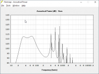
Here's an SB Acoustics SB17 in a 32L enclosure tuned to 37Hz with an F3 of 34Hz

Here's the same woofer in a 41.2L enclosure tuned to 28Hz and 68Hz with an F3 of 27Hz

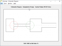
Here's the vented enclosure diagram

Here the series tuned bandpass diagram

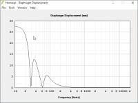
Here's the vented displacement

Here's the series tuned bandpass displacement
Series tuned bandpass is a real strange box. It's actually a challenge to get the F3 up to 27Hz. I could probably get it down to 20Hz or even lower with little effort. This alignment can play REALLY low. But you can see from the sims that the design becomes severely limited by displacement in a hurry. You could probably throw together a series tuned bandpass that will run out of displacement with 1-10 watts! This is probably one of the reasons that Bose used it for ages, you could easily get 30Hz from a couple of five inch woofers. But they won't be able to take much power, due to displacement limits. Due to Hoffman's Iron Law the series tuned bandpass has lower efficiency. You could easily get the efficiency up higher if you wanted to. I intentionally kept the size small because I wanted to make a "fair" comparison to the vented box.
It would be fun to compare this to a tapped horn.
qustion.
for the internal vent betwwen Ch1 and 2, What is the max port air velocity you want to keep?
Are there rules of thumb with regards to Sd of the driver for not getting out of control?
for the internal vent betwwen Ch1 and 2, What is the max port air velocity you want to keep?
Are there rules of thumb with regards to Sd of the driver for not getting out of control?
seems like if the internal vent is too small then it will choke but chuffing might not be heard.
Last edited:
I've always dreaded dual reflex bandpass boxes. I used to build a TON of these in the early nineties. This was in the dark days of car audio when a typical amplifier cost the equivalent of $500 in today's money, and put out 50 watts x 2. So I built a lot of dual reflex boxes to get the efficiency up.
I haven't built one in 25 years. I soured on them, because they're REALLY easy to screw up. Series tuned bandpass boxes are hideously complex because there's at least seven variables that can screw up the response:
7) size of the rear chamber
6) size of the front chamber
5) length of rear port
4) length of front port
3) height of the front chamber
2) depth of the front chamber
1) offset of the driver
So I'd avoided making one, because they're just so easy to screw up. On top of all that, I've never seen a reliable way to design one.
To me, the obvious way to make a series tuned bandpass box (bp6) would be to design a ported box for a driver, then stick a chamber in front and add a port to the front.
That doesn't work. If you try that, you generally wind up with two massive peaks, or even just one.
As if that wasn't bad enough, if you don't tune the vents carefully, you can actually wind up with a HUGE box that's NOT efficient. The vents are acting as acoustic filters, so if the vents aren't working properly, it's quite easy to wind up with a one note wonder, or an inefficient box, or both.
At this point, I hope I've discouraged 80% of the people who might build one, because building one is a TERRIBLE idea if you don't have a microphone and you know how to use Hornresp.
But if you do...
Here's how to make a series tuned bandpass box.
There may be a better way to do this, and if there is, please post a response. But the method I am about to describe is working for me.
Step 1:
The first step is to focus on the OVERALL volume of the subwoofer. I'd originally focused on using a specific volume for the rear chamber, and then guessing at the front chamber. That doesn't seem to work. What DOES seem to work is to choose an overall volume for the box. One place to start is to use a volume that's 50% larger than what you would use for a vented box with the same driver.
Step 2:
The second step is to set the length of the front port to a VERY short length. I used 1.27cm (one half inch.)
Step 3:
The third step is to set the length of the rear port so that the response is flattish
And that's it! At this point, you can call it a day, you will have a semi-functional series tuned bandpass box.
Of course, The Devil is in the Details, and here's where things get fun.
I know this is a long and boring post, but this next part is important, if you want to build one of these subs:
When you make the port in the FRONT box longer, it lowers the tuning frequency of the entire design. Because of this, you can compensate by making the port in the rear chamber SHORTER.
So this becomes like a "see saw." When you make the length of the front port longer, you'll need to make the length of the rear port SHORTER.
The thing that's interesting, is that you can use this process to do some really strange things. For instance, you can a have a series tuned dual reflex bandpass box that plays MUCH lower than a conventional vented box. You can also manipulate these acoustic filters (also known as "ports") to achieve narrow bandwidth with high efficiency.

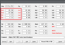
Here's a sim I did, using an Alpine SWS-10D2. The vented box is an SBB4 alignment, done with a calculator. It's a bit shy of one cubic foot. The BP6 box is about 50% bigger. The BP6 box plays about 15% lower, with about the same efficiency. (It IS bigger.) The cool thing is, you can juggle the variables all you want. For instance, you could sacrifice efficiency for an F3 that's even lower.
The complexity of these BP6 boxes is daunting. But it's a type of subwoofer which allows you to get a driver to play REALLY low.
If you have a driver that would normally play down to 30Hz in a vented box, with a BP6 box you can generally get it to play about half an octave lower.
I haven't built one in 25 years. I soured on them, because they're REALLY easy to screw up. Series tuned bandpass boxes are hideously complex because there's at least seven variables that can screw up the response:
7) size of the rear chamber
6) size of the front chamber
5) length of rear port
4) length of front port
3) height of the front chamber
2) depth of the front chamber
1) offset of the driver
So I'd avoided making one, because they're just so easy to screw up. On top of all that, I've never seen a reliable way to design one.
To me, the obvious way to make a series tuned bandpass box (bp6) would be to design a ported box for a driver, then stick a chamber in front and add a port to the front.
That doesn't work. If you try that, you generally wind up with two massive peaks, or even just one.
As if that wasn't bad enough, if you don't tune the vents carefully, you can actually wind up with a HUGE box that's NOT efficient. The vents are acting as acoustic filters, so if the vents aren't working properly, it's quite easy to wind up with a one note wonder, or an inefficient box, or both.
At this point, I hope I've discouraged 80% of the people who might build one, because building one is a TERRIBLE idea if you don't have a microphone and you know how to use Hornresp.
But if you do...
Here's how to make a series tuned bandpass box.
There may be a better way to do this, and if there is, please post a response. But the method I am about to describe is working for me.
Step 1:
The first step is to focus on the OVERALL volume of the subwoofer. I'd originally focused on using a specific volume for the rear chamber, and then guessing at the front chamber. That doesn't seem to work. What DOES seem to work is to choose an overall volume for the box. One place to start is to use a volume that's 50% larger than what you would use for a vented box with the same driver.
Step 2:
The second step is to set the length of the front port to a VERY short length. I used 1.27cm (one half inch.)
Step 3:
The third step is to set the length of the rear port so that the response is flattish
And that's it! At this point, you can call it a day, you will have a semi-functional series tuned bandpass box.
Of course, The Devil is in the Details, and here's where things get fun.
I know this is a long and boring post, but this next part is important, if you want to build one of these subs:
When you make the port in the FRONT box longer, it lowers the tuning frequency of the entire design. Because of this, you can compensate by making the port in the rear chamber SHORTER.
So this becomes like a "see saw." When you make the length of the front port longer, you'll need to make the length of the rear port SHORTER.
The thing that's interesting, is that you can use this process to do some really strange things. For instance, you can a have a series tuned dual reflex bandpass box that plays MUCH lower than a conventional vented box. You can also manipulate these acoustic filters (also known as "ports") to achieve narrow bandwidth with high efficiency.
Here's a sim I did, using an Alpine SWS-10D2. The vented box is an SBB4 alignment, done with a calculator. It's a bit shy of one cubic foot. The BP6 box is about 50% bigger. The BP6 box plays about 15% lower, with about the same efficiency. (It IS bigger.) The cool thing is, you can juggle the variables all you want. For instance, you could sacrifice efficiency for an F3 that's even lower.
The complexity of these BP6 boxes is daunting. But it's a type of subwoofer which allows you to get a driver to play REALLY low.
If you have a driver that would normally play down to 30Hz in a vented box, with a BP6 box you can generally get it to play about half an octave lower.
Last edited:
Hi PB,
Thanks, you have unwittingly unearthed a minor bug in Hornresp 🙂.
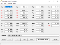
The Vc1, Vc2, S3, S4, Lc1, Lc2, Lo1 and Lo2 labels shown on your BP6S Input Parameters window screenprint should be coloured black, not red. It took me a while to work out how this could possibly happen, but it transpires that if a previously-saved record with stepped segments is changed to a band pass record, the red labels switch to black as intended but after the modified record is then saved and subsequently re-opened, the labels revert to red, as shown in the attachment.
This will be fixed in the next release.
Kind regards,
David
Thanks, you have unwittingly unearthed a minor bug in Hornresp 🙂.
The Vc1, Vc2, S3, S4, Lc1, Lc2, Lo1 and Lo2 labels shown on your BP6S Input Parameters window screenprint should be coloured black, not red. It took me a while to work out how this could possibly happen, but it transpires that if a previously-saved record with stepped segments is changed to a band pass record, the red labels switch to black as intended but after the modified record is then saved and subsequently re-opened, the labels revert to red, as shown in the attachment.
This will be fixed in the next release.
Kind regards,
David
Attachments
On another thread, BP1Fanatic wrote:
"I love this thread!
I see PB and I agree on BP enclosures! Although, I look at TH, T-TQWT, and TQWP as BP6S enclosures.
SPL competition = subjective, only numbers matter.
SQ competition = objective, judged opinions."
I decided to try that out, and lo and behold, he's right! What a trip: a tapped horn is basically a series tuned bandpass box.
Here's how I tested this:
I made a tapped horn in hornresp, but I staggered it so that:
4) the volume of S1-S2 is equivalent to the back chamber of the series tuned banpass from post 37
3) the volume of S3-S4 is equivalent to the front chamber of the series tuned banpass from post 37
2) the length and volume of S2-S3 is equivalent to the rear port
1) the length and volume of S4-S5 is equivalent to the front port
Once I did that, the response and the impedance curve of this "tapped horn" is basically the same as the series tuned bandpass box from post #37
Attachments
A gentleman in another group who was familiar with qw (he had a paraflex plan from MMJ he had built, and was building a BP6 enclosure for something else entirely. He was having a hard time and I didnt like(wasn’t familiar) with tHe BP sections of HR, so I asked if I could switch it and I thought it might be ‘easier’. Not only was it easier, but anyone familiar with qw will find it a godsend IMHO! Truely makes it a smooth and not frustrating experience.
That said, can we then put a Vented Rear Chamber into this subject? This part has me by the balls. Stretching the idea out again from Trutucums original posting .... where can I sneak past parallel, as in CH(with ‘path’ designated as the wood panel between exit center lines of them... and instead use TH and L45(orL34 if a 3 segment Horn) at 0.01cm..? How should I interpret this if I’m bending the rules in an effort to gain input features specific to certain sims in HR, missing in others? An exp horn shape in 3 PAR segments and a fancy rear vented chamber shape that squeezing into the foldings as a stub or actual end fired rear vented chamber...? Either is fine, but bending the rules is leaving too much on the table at risk. Youve all likely seen the ugly that lurks in between these seperates if not appropriately sharing the passband contributions(TH is nasty, ’path’ versions of rear vented/ qw pipes(conpound) is almost as brittle). I can provide some HR sim shots to point it out... but series/parallel or both quickly can be diluted in a Fold that puts ‘direct radiator’ and ‘horn’ as a near ZERO a ‘path’ 😱
?? Any words of wisdom?
- Home
- Loudspeakers
- Subwoofers
- Parallel vs Series Tuned 6th order bandpass boxes