Thank you for your help, It's almost clear now 🙂
If I have the time tomorrow, I'll try to draw a schematic of what I understood. An image tells more than a thousand words 😉 I think it will be easier for you to tell me if I'm right or wrong, and to see where I'm wrong.
Alex
If I have the time tomorrow, I'll try to draw a schematic of what I understood. An image tells more than a thousand words 😉 I think it will be easier for you to tell me if I'm right or wrong, and to see where I'm wrong.
Alex
some prictogramms for better understanding please...
great Bricolo, you understood it, please teach me now. I wait for you drawing.
great Bricolo, you understood it, please teach me now. I wait for you drawing.
Just do like me, ask questions 😉
I'll try to give you an answear. And if I can't or if I'm wrong in my answear, Thorsten will certainly tell what he thinks too
I'll try to give you an answear. And if I can't or if I'm wrong in my answear, Thorsten will certainly tell what he thinks too
Kuei Yang Wang said:Konnichiwa,
The DAC has a digital +5V Supply and +/- supply for the "analogue" section. Hence it has two "PSU common" (aka -V in case of positive supplies) pins, which should be used to form independent supply current loops. I really cannot explain it any better, sorry.
I have/had somewhere an expanded set of details, but the -15V and the +6V (in most Philips applications this is 6V not 5V) are the analogue section and there is a corresponding PSU pin, the other PSU Pin and Ground are logic.
...
To my information -15 is analog and +5 and -5 are digital supplies.
Could be wrong, only read this on the net at some locations.

Greetings,
Konnichiwa,
To be sure I'd need to look up a lot of stuff that's in tha attic and it will take time which I don't have. So someone else please check.
Sayonara
guido said:To my information -15 is analog and +5 and -5 are digital supplies.
Could be wrong, only read this on the net at some locations.
To be sure I'd need to look up a lot of stuff that's in tha attic and it will take time which I don't have. So someone else please check.
Sayonara
quido seems right, that's what I found on google
http://users.podolsk.ru/boga/DAC.html
http://www.diyaudio.com/forums/showthread/t-8193.html
http://users.podolsk.ru/boga/DAC.html
http://www.diyaudio.com/forums/showthread/t-8193.html
Thorsten, for something really more available to DIYers
What whould be the best way to design a PCB on a single layer self made board?
What whould be the best way to design a PCB on a single layer self made board?
parallel
Hi Kuei Yang Wang,
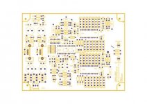
this is the topscreenof the PCB. CS8414/8412 with parallel TDA1541a only.
any comment to correct??
thanks
thomas
www.diyaudiocraft.com
Hi Kuei Yang Wang,
this is the topscreenof the PCB. CS8414/8412 with parallel TDA1541a only.
any comment to correct??
thanks
thomas
www.diyaudiocraft.com
Attachments
parallel
Hi bricolo,
these website below were informations for me to reference.
http://users.podolsk.ru/boga/DAC.html
http://hjem.get2net.dk/torbenk/dualdactube.htm
http://www.ndh.net/home/kboehm/T-DAC-P2.htm
But something I was improve already.
Pls take a look. Hope can help U.
cheers
thomas
www.diyaudiocraft.com
Which supply pins are analog?

Refering back to the question over which supply pins are digital and which are analog...
I personally think that the -15V and -5V (or 6V in most Philips applications) are analog and the +5V is digital. This is based on the fact that the DEM reclocking circuit is referenced to the -5/6V pin (see DEM reclocking circuit posted on this forum). We all know that oscillators such as the DEM oscillator are analog so I think that the -5/6V supply is analog.
At least that is what I think...now I will have to redo my DAC grounding, and try -6V instead of -5V to see if there is any difference in sound quality.
Hi,
I also think that some drawings would be good because terms like "supply return pin" and that kind may mean anything.
I also think that some drawings would be good because terms like "supply return pin" and that kind may mean anything.
Re: Which supply pins are analog?
Maybe, maybe not 😕
Maybe he just needed -6 and used the ps available. I am going to ask him, we have an email conversation ongoing about his DEM circuit (more about the why on reclocking WS).
Greetings,
Guido
PS The conclusion on WS is that it is not beneficial in i2s mode....
Zodiac said:
Refering back to the question over which supply pins are digital and which are analog...
I personally think that the -15V and -5V (or 6V in most Philips applications) are analog and the +5V is digital. This is based on the fact that the DEM reclocking circuit is referenced to the -5/6V pin (see DEM reclocking circuit posted on this forum). We all know that oscillators such as the DEM oscillator are analog so I think that the -5/6V supply is analog.
At least that is what I think...now I will have to redo my DAC grounding, and try -6V instead of -5V to see if there is any difference in sound quality.
Maybe, maybe not 😕
Maybe he just needed -6 and used the ps available. I am going to ask him, we have an email conversation ongoing about his DEM circuit (more about the why on reclocking WS).
Greetings,
Guido
PS The conclusion on WS is that it is not beneficial in i2s mode....
Put some details up
Guido,
Would be interesting if you put the key points of your exchanges with Henk up in the DEM thread. I did the DEM reclocking, worked a treat, and my TDA1541 is in I2S mode....
p.s. 4Fs sounds much better than 8Fs for the DEM circuit
I agree though about the -6V. Ask him!
Guido,
Would be interesting if you put the key points of your exchanges with Henk up in the DEM thread. I did the DEM reclocking, worked a treat, and my TDA1541 is in I2S mode....
p.s. 4Fs sounds much better than 8Fs for the DEM circuit
I agree though about the -6V. Ask him!
Re: Put some details up
I'll ask about that too, maybe my comment on WS is already 'out of line'... 4Fs probably sounds better because of the speed the circuit can handle. Depends what your Fs is... (os or non-os).
Reclocking of WS has nothing to do with the DEM modification
Gr,
Zodiac said:Guido,
Would be interesting if you put the key points of your exchanges with Henk up in the DEM thread. I did the DEM reclocking, worked a treat, and my TDA1541 is in I2S mode....
p.s. 4Fs sounds much better than 8Fs for the DEM circuit
I agree though about the -6V. Ask him!
I'll ask about that too, maybe my comment on WS is already 'out of line'... 4Fs probably sounds better because of the speed the circuit can handle. Depends what your Fs is... (os or non-os).
Reclocking of WS has nothing to do with the DEM modification
Gr,
Re: Put some details up
Zodiac,
Thanks for comparing the two DEM frequencies.
Henk used -6V because that's just what's typically available in Philips cd players. I have -6.25Vdc for this supply.
-5V should work just fine...
😎
Zodiac said:Guido,
Would be interesting if you put the key points of your exchanges with Henk up in the DEM thread. I did the DEM reclocking, worked a treat, and my TDA1541 is in I2S mode....
p.s. 4Fs sounds much better than 8Fs for the DEM circuit
I agree though about the -6V. Ask him!
Zodiac,
Thanks for comparing the two DEM frequencies.
Henk used -6V because that's just what's typically available in Philips cd players. I have -6.25Vdc for this supply.
-5V should work just fine...
😎
It is quick to compare
Rudolf,
I'm not quite sure how you set up your DEM board but comparing the two frequencies is easy - just move one connection on the frequency divider chip. I used 74HC163s for this purpose....
One thing that made me try the 4Fs instead of 8Fs is that if you look at the TDA1541 (not A) data sheet (with the onboard DEM capacitor) it states that 200kHz is normal DEM oscillator frequency. 4fs is 176.4kHz and 8Fs is 352.8KHz, thus it also makes some sense from an engineering perspective
Guido,
Just for reference, my TDA1541 implementation is non-o/s. I came across an interesting article on the web which may go some way to explaining why reclocking all three lines makes an audible difference.
http://www.stereophile.com/interviews/850/index1.html
It refers to the fact that the TDA1541 doesn't like to see noise at its input pins. Makes sense....
One day I might actually stop fiddling around with my TDA dac and actually play some music on it!!
Re: It is quick to compare
I know it's easy to compare Zodiac, I just never bothered.
I already knew the internal TDA1541 logic wouldn't be fast enough at higher frequencies.
Seems we had the same reasoning based on the 200kHz 🙂
I know it's easy to compare Zodiac, I just never bothered.
I already knew the internal TDA1541 logic wouldn't be fast enough at higher frequencies.
Seems we had the same reasoning based on the 200kHz 🙂
Great minds think alike....or is that fools seldom differ 😉
Any1 got any further insight on which supply pins are for digital which for analogue?
Any1 got any further insight on which supply pins are for digital which for analogue?
- Status
- Not open for further replies.
- Home
- Source & Line
- Digital Source
- Parallel TDA1541A non-o/s DAC Kits