SimontY said:
In a x.5 way design these two are the same thing.
OK, no worries. So the baffle step is at 1/3 wavelength. That works out to 380 Hz for a 0.3m wide enclosure.
Interestingly, I have just finished reading through the chapters on enclosure design and crossovers, and there is not mention of baffle step 😕
Cheers,
Glen

Any line array affectionados out there who can testify as to the sound and polar response of ~500Hz woofer arrays?
G.Kleinschmidt said:
...... and there is not mention of baffle step 😕
Cheers,
Glen
Hi,
Really ? I am surprised ......
Beaming is an issue for a single driver, but lobing and hence
constructive / destructive interference and assymetrical
beaming are all issues for arrays of multiple drivers.
Problems are above when wavelength = ~ 1/2 array length.
looking at http://www.zaphaudio.com/ZDT3.5.html
Is worthwhile as the all the BSC is in the bass section.
Which is 0.5 way for best mid integration.
Zaph comprehensively discusses the vertical dispersion issues,
I'll note said "issues" are peanuts compared to to some of the
multiple driver layouts mentioned in this thread.
Even in this case there is some vertical droop at 500Hz.
For all BSC in the bass 2 drivers are better than 4, 0.5 way better.
In this case MTM mid treble seems pointless, 1 4ohm driver ?
http://www.deadwaxcafe.com/vzone/david/david.htm
Is worth reading for yet another approach to BSC.
Crossing over bass to mid lower is of course an option, but then
the senstivity numbers start moving around for the same drivers.
Well designed and documented 3 ways are very thin on the ground.
As for that matter are decidated high quality midrange drivers ....
IMO 2 x10" 4ohm drivers is likely a better option than same cost 4 x 8".
🙂/sreten.
Well, since the discussion has gone beyond concept and into practical issues, there is little I can add, but BOY am I learning a lot.
For a quick and easy overview of Baffle Step, here are two source which are short easy reads, but at the same time authoritative -
Elliot Sound - Baffle Step Compensation
http://sound.westhost.com/bafflestep.htm
True Audio - Loudspeaker Diffraction Loss and Compensation
http://trueaudio.com/st_diff1.htm
All Tech articles from both sources-
http://sound.westhost.com/articles.htm
http://trueaudio.com/st_index.htm
Like I said, a quick and easy overview.
Steve/bluewizard
G.Kleinschmidt said:
The amp can deliver 1600W into 0.5 ohms in class AB without clipping.
20 pairs of BJT output devices were required to meet the dissipation requirements of the 200W into 4 ohms classs A specification. A byproduct of this is an output stage capable of delivering huge output current in class AB into low impedances.
Cheers,
Glen

Glen, I've not read this entire thread but what you say makes perfect sense, and based on what I've seen of your design work I think you can handle it just fine.
I did a four way first order in college before graduating, and was very pleased with the results. It was inspired by the Dahlquist DQ-10s and IMF transmission lines. I really prefer roughly 2nd order electrical, 4th order LR for most of my designs now, but 1st order can be made to work. It is even more difficult in a high powered systems because of the gradual rolloff rates, you'll have to make careful driver choices.
I've also thought that the Hi Fi world should shift to a lower impedance standard, since as I'm sure you know it is a better match for the SOA in solid state amps.
Use 4 ohm drivers and put them in parallel. You might get away with 8 ohm units above the bass as a result of baffle step compensation. You will use the power, it is needed in the bass. You might even use 4 ohm DVC drivers and put them all in parallel.
You might want to have a look at the AR-9s where two 4 ohm bass drivers were used in parallel, however they added a resoanant circuit to bring the impedance back up.
I started this thread just as a thought exercise, never expected it to cause so much controversy, might give you some ideas:
http://www.classicspeakerpages.net/IP.Board/index.php?showtopic=1189&hl=fora-9
My advice, be aware of the limitations of first order networks:
Poor out of band rejection which compromises distortion and power handling.
Poor off axis lobing.
It is difficult to get an electro-acoustic 1st order response after the XO response is cascaded with the driver's acoustical response. Think wide band drivers, phase compensation networks, compromising time alignment to get the phase right.
Use baffle step compensation which will probably include your W, M1 and perhaps M2 drivers.
Remember to allow for inductor DCR when recalculating driver Qts so that you do not end up with something that cannot be implemented at a reasonable cost.
Get a good speaker simulation and measurement system.
You might consider using 2nd-3rd order electrical for the tweeter M2 crossover since the tweeter is most fragile.
How about an NHT-3.3 with two woofers, it is 4 ohms to start so 2 ohms in the bass with two. In fact a W-M1-M2-T-M2-M1-W tower version might be interesting:
http://www.diyaudio.com/forums/showthread.php?s=&postid=1545178#post1545178
The woofers are a bit on the inefficient side, the 10" version is even worse, might want to substitute. The non-linear data is available for the other drivers and the lower mids are also not very good, might want to substitute a SCAN. I like the upper mid, and there are many choices for tweeters.
Another thought, considering all the power that you have available, and that this should be an ultimate system, it would not be unreasonable to have 4 12" woofers per side. You could do 2 facing forward, and 2 back or side, with these 2 being for baffle step comp only. You may then want to LT transform the bass response so that you can use a smaller box.
I wrote this concerning vented systems in case you're interested:
http://www.diyaudio.com/forums/showthread.php?postid=1260665#post1260665
Pete B.
Well, I did suggest the Hivi M12, a 4ohm 12"...but I dont know how high you need to cross, and I would prefer to listen to the raw system before making any assumptions
http://www.swanspeaker.com/product/htm/view.asp?id=84
Or else take a closer look at AE drivers, ok they are not 4ohm, but whats the point of chasing a wild goose, rather than going safe and fore upmost quality
http://www.aespeakers.com/drivers.php?driver_id=4
Making speaker designs just like this is not so easy, its difficult enough on its own
Nice one, Xmax is not so large though.
I like these but have not tried them:
http://www.diycable.com/main/product_info.php?products_id=653
Two per side would probably be enough given their VD.
Oh sure the Lambda drivers are real nice, John might make them for him in 4 ohms if he asks. Or even 2 for that matter.
Pete B.
I like these but have not tried them:
http://www.diycable.com/main/product_info.php?products_id=653
Two per side would probably be enough given their VD.
Oh sure the Lambda drivers are real nice, John might make them for him in 4 ohms if he asks. Or even 2 for that matter.
Pete B.
PB2 said:Nice one, Xmax is not so large though.
If you mean the M12 Hivi, it has 10mm airgap and 24mm voice coil height, thats 14mm p-p, which I think is a lot of movement fore a 93db 12" hifi woofer
The Exodus will probably go pretty deep, but I have doubts about it filling in BSC, but who knows, with proper xo...maybe
This B&C PRO mid would take some serious beating, its 92db
http://www.bcspeakers.com/index.php?sez=1&categoria=2&id_descrizione=44&prodotto=194
This AE is 4 ohm, don't see a figure for cone mass:
http://www.aespeakers.com/drivers.php?driver_id=6
Anyone have or seen FR plots for the Shiva-X, not sure how high into the mid bass it will go?
Pete B.
http://www.aespeakers.com/drivers.php?driver_id=6
Anyone have or seen FR plots for the Shiva-X, not sure how high into the mid bass it will go?
Pete B.
That particular AE does seem to be 4ohm, but it has VERY low Qts which means its low on deep bass...maybe its possible to order 4 other AE woofers with 4ohm ?
Yes Qts is low, this will allow him to use a lower cost higher resistance inductor, but I agree it might be too low, have to try simulating it. It simply means that the magnet is too strong, ask John for a smaller magnet.
The advantage of these, as I think you know, is that they play clean well into the midbass, and would allow a higher XO point. They also have a lot of copper in the motor for obvious reasons.
Might allow Glen to get away with a 3-way.
The advantage of these, as I think you know, is that they play clean well into the midbass, and would allow a higher XO point. They also have a lot of copper in the motor for obvious reasons.
Might allow Glen to get away with a 3-way.
Great thead guys, took me awhile to read through but was worth it.
Glen your lucky to have so many folks willing to pitch in a well thought out suggestion.
Nothing I can add but I will say I recently did a 2nd order 3.5way WMTMW and it wasn't trivial even with a modern approach. Lots of work, lots of measurements but eventually I found something that measured OK but, more importantly, sounds right.
in-room far field on axis freq. response
Step response from same position as the above
Make it as pretty or as utilitarian as you like but I think its going to be tough to get a good sounding 1st order 3 or 4 way. As you can see 2nd order is very possible with a little care in driver choice and, as other have suggested, I think this is where your better off looking IMO.
Glen your lucky to have so many folks willing to pitch in a well thought out suggestion.
Nothing I can add but I will say I recently did a 2nd order 3.5way WMTMW and it wasn't trivial even with a modern approach. Lots of work, lots of measurements but eventually I found something that measured OK but, more importantly, sounds right.
in-room far field on axis freq. response
An externally hosted image should be here but it was not working when we last tested it.
Step response from same position as the above
An externally hosted image should be here but it was not working when we last tested it.
An externally hosted image should be here but it was not working when we last tested it.
Make it as pretty or as utilitarian as you like but I think its going to be tough to get a good sounding 1st order 3 or 4 way. As you can see 2nd order is very possible with a little care in driver choice and, as other have suggested, I think this is where your better off looking IMO.
Shin, some questions to your beautiful speaker
Low 0.5 mid...being an active speaker, how do you do that 0.5way thing ?
And the hard one...If you should do it again, is there something you would do differently ?
Low 0.5 mid...being an active speaker, how do you do that 0.5way thing ?
And the hard one...If you should do it again, is there something you would do differently ?
tinitus said:Shin, some questions to your beautiful speaker
Low 0.5 mid...being an active speaker, how do you do that 0.5way thing ?
Hi tinitus
Are you asking how the crossover is worked to sum the two drivers flat(at least on axis) in their overlap region?
If so its done using FIR filters which makes the job much easier. Everything is digital.
If you look at these filters
An externally hosted image should be here but it was not working when we last tested it.
red = bass to 200hz
brown = lower mid 200-600hz
green = upper mid 200-2500hz
blue = treble 2500hz+
The black line shows they sum flat when they're added together.
To get this result, the brown filters overall gain is lowered 6dB and the green filter, for the upper midrange that covers the larger range, has had the resultant brown filter mathematically subtracted in the time domain. This allows the two to sum correctly over the region where they overlap.
Result is elimination of comb filtering that would otherwise result from a 3-way design and your still decreasing distortion over the baffle step with two drivers working there. I tried really hard to get a good sounding 3-way but I came to the realisation that my mids were spaced too far apart to do make this a reality so I went the 3.5way solution presented here.
And the hard one...If you should do it again, is there something you would do differently ?
Hmm...
Well I'd originally intended the whole thing to be a 3way design but that never met my expectations. You see for that to have worked I'd have needed much closer spacing on the mids. I made the mistake of thinking it wasn't such a huge deal and the large ribbon between the two mids plus the cabinet design meant that I was running two 5" drivers upto 2.5Khz with a center to center spacing of around 35cm. This produced horrible combing artifacts off axis creating an uneven and unnatural reverberant soundfield(sound you hear from reflections within a room). I tried band aids such as lowering the tweeter crossover to 1.5Khz and using very steep steep filtering such as the Neville/Thiel types but this resulted in a different kind of unsatisfactory sound.
Only when I switched to the 3.5way did things drop into place with both the measurements and what I was hearing. Even then it took a lot of work to get it sounding its best but that's one of the fun things about this hobby.
As for the rest of the design I don't think I'd do it any differently.
And here is me thinking all along that 3.5 was used only to boost low bass to make up for lack of sonic power down low.
Theres wrong, really wrong and reaallly reaaalllly wrong, I think I know where I sit;; but do my efforts sound good to me because I've not been able to do real time comparisons.
Let me put that another way; I know when I've made a mistake-- because what I've built sounds bad to me, but when it sounds good to me how do I know it's right??
I know it's probably time to buy some measuring tools but honestly is it really worth the cost?? I'd need new computer ( for a good quality sound card)
Glenn-
You seem to have all the BSC info nailed down (from post 171).
You only need a 90dB senstive midrange or so. I prefer not to pad down the midrange too much.
I know there was a question about 4 8" drivers due to vertical response lobing. The best thing to do is calculate the difference in phase that you will get between the closest driver and the furthest driver. Calculate this for different distances from the speaker. I suspect you can find a woofer arrangement that will minimize the response lobing.
I really "listen" seated in one spot. How the sound changes is not an issue, because if I am moving around, I am not seriously listening anyway.
The last speakers I built were WWWWMT, using the Dayton RS150-4 as woofers. (which I don't recommend, the bass does not go deep enough). But they do sound great.
JJ
Whhooaaaa.......
Thanks guys for all the input since my last post. I'm not ignoring anyones input, but I’m on a very steep learning curve here so there is a lot to take on board.
Following on from my previous musings, for now I would like to persist with the design issues and limitations of the WWWWMT layout. I’m not trying to be stubborn here; I just want to comprehensively learn what the problems are, before deciding on another approach without properly appreciating the reasons for doing so 🙂
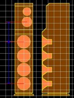
I’ve attached a conceptual drawing below.
I’ve got the four 8-ohm, 8” Visaton 84dB woofers at the bottom in a fully sealed enclosure.
The baffle step will occur at approximately 350Hz and the woofer centres are spaced 0.23m each for an array length of 0.69m.
Suppose I cross the woofers over at approximately 350Hz to take care of the baffle step. 350Hz has a wavelength of 0.971m.
Would this crossover be sufficiently low to avoid lobing issues with the woofer array?
The other issue is the location of the mid-range driver. Its centre is located 0.675m from the centre of the woofer array. This is still less than the 0.971m wavelength of the 350Hz crossover, but is it enough?
The isobaric woofer array will have a sensitivity of 84dB+12dB = 96dB. Supposing an ideal (?) baffle step gain of +6dB, the mid-range driver and tweeter will require at least 90dB sensitivity.
Would it be feasible to find a +90dB mid-range driver with a sufficiently low resonant frequency for the 350Hz lower crossover as well as wide enough bandwidth to extend to the tweeter crossover, without needing a brutal crossover filter (which has to be implemented passively)?
Cheers!
Glen
Thanks guys for all the input since my last post. I'm not ignoring anyones input, but I’m on a very steep learning curve here so there is a lot to take on board.
Following on from my previous musings, for now I would like to persist with the design issues and limitations of the WWWWMT layout. I’m not trying to be stubborn here; I just want to comprehensively learn what the problems are, before deciding on another approach without properly appreciating the reasons for doing so 🙂
I’ve attached a conceptual drawing below.
I’ve got the four 8-ohm, 8” Visaton 84dB woofers at the bottom in a fully sealed enclosure.
The baffle step will occur at approximately 350Hz and the woofer centres are spaced 0.23m each for an array length of 0.69m.
Suppose I cross the woofers over at approximately 350Hz to take care of the baffle step. 350Hz has a wavelength of 0.971m.
Would this crossover be sufficiently low to avoid lobing issues with the woofer array?
The other issue is the location of the mid-range driver. Its centre is located 0.675m from the centre of the woofer array. This is still less than the 0.971m wavelength of the 350Hz crossover, but is it enough?
The isobaric woofer array will have a sensitivity of 84dB+12dB = 96dB. Supposing an ideal (?) baffle step gain of +6dB, the mid-range driver and tweeter will require at least 90dB sensitivity.
Would it be feasible to find a +90dB mid-range driver with a sufficiently low resonant frequency for the 350Hz lower crossover as well as wide enough bandwidth to extend to the tweeter crossover, without needing a brutal crossover filter (which has to be implemented passively)?
Cheers!
Glen
Attachments
jupiterjune said:I really "listen" seated in one spot. How the sound changes is not an issue, because if I am moving around, I am not seriously listening anyway.
I fell into the same trap but never again. On axis sound is only part of the story and on axis measurements are insignificant really.
Uneven polar response with big irregularities such as combing creates an unconvincing sound where tonality, sense of space and the general believability falls short. Subjectively, I found out through my own experiments that your constantly being reminded that your listening to speakers when this is ignored.
It doesn't matter whether you sit down or do whatever, the speaker radiates sound in directions other those that lead straight to your ear. Its important IMO to have the off axis response relatively flat.
Member
Joined 2002
- Status
- Not open for further replies.
- Home
- Loudspeakers
- Multi-Way
- Parallel driver interaction in a 4-way system.