Originally posted by sreten
What are you trying to demonstrate :
The normal class A quality into a sensible load ?
The class AB quality into poor loads ?
[/B]
G.Kleinschmidt:
I already stated quite clearly the intentions for the design in the very first paragraph of the *******g post that you quoted.
Glen, I think you are misunderstanding Sreten. Also, no need to be so defensive; it doesn't hurt to restate your goals, and your goal really were not that clear in your original post. True, they did become clearer as the thread grew, but I didn't understand your underlying purpose until quite a few posts into this thread.
So, my point, restating your goals and purpose in new words now and then doesn't hurt.
Now to the main point, in a round-about way, Sreten is asking what I've been asking (in my own round-about way).
My interpretation is -
"What are you trying to demonstrate?"
"The normal class A quality into a sensible load ?"
To me this is Sreten saying - isn't your real long term goal rock solid unerring fidelity?
"The class AB quality into poor loads ?"
Rather than the arc welder like current sourcing capability?
True, being able to demo low impedance loads proves that the amp is stable and with great capabilities. But again, driving low loads just to be driving low loads is pointless, unless of course you really are designing arc welders.
In daily practice, you want this immense stability and mammoth current sourcing capability to enhance the normal high fidelity listening experience.
So, again, by my interpretation, Sreten is just saying, when it comes to building speakers for this amp, concentrate on quality and fidelity, not on quantity and current demand. Which is exactly what I'm saying. Whatever you decide for speakers should be a decision made to maximum quality of sound, and that in turn, will show off the stability of your amp.
No one is criticizing your Amp. No one is even criticizing your evaluation of varying speaker impedances. We all absolutely agree that this is one fantastic amp. What we are criticizing is your apparent obsession with driving low impedance for the sake of driving low impedance.
Now that you have both Quality and Quantity in your amp, concentrate on pure quality for the speakers, and the resulting impedance will be what ever it will be. Low impedance, in and of itself, shouldn't be a goal, though at times low impedance can be the inevitable and unavoidable result of trying to achieve a particular high fidelity design. But again, it is an unavoidable result, not a goal.
Now that you have this Quality Amp, your goal should be Quality Speakers for the sole purpose of producing the [/i]Highest QUALITY Listening Experience[/i].
The demo of the extreme current sourcing capability of this amp, should be little more that a novelty on the side.
So, once again, low impedance for the sake of low impedance just dumps current down the drain all day long. Yes, without a doubt, it is an important characteristic in an amp, but again, now that you have the amp, your next goal should be the best absolute fidelity in your speakers that is possible within your skill level and budget.
Your amp would do much better to drive an 8 ohms load or a 4 ohms load with unerring fidelity than it would to dump current into a 2 ohm load all day long. Plus, if your resulting speakers are in the 4 ohm or 8 ohm range, that means in the future, for what ever reason, you can still add a second set of speakers and maintain very high fidelity even the resulting low load.
So, once again I ask, do you see my point? Do you see what I am getting at here?
You goal is and always should have been Quality not Quantity. Likely your amp, much to its advantage, has both. But don't compromise the quality of the amp, by misplace objectives in the speakers. Quality of sound and experience should be the first and foremost goal.
Just rambling on.
Steve/bluewizard
SimontY said:Wouldn't a simple way of reaching the goal be a line-array?
Something like a tweeter, one mid, then eight (8 ohm) bass drivers wired in parallel for a 1 ohm nominal load.
Simon
Spot on, with loads of Eq 😉
But it aint that easy to get the sensitivities right
We are giving you very high quality advice Glen, you should not complain if it does not match your misconceptions about speakers.
Have you done some research on the reasons why the impedance of WATT/Puppy speakers dips to 2 ohms? It's by design. The system is comprised of a full-range enclosure and a subwoofer enclosure with a poorly designed passive crossover between both. As a result, the impedance dips to 2 ohms at 100Hz. A powered subwoofer would solve the problem. There are many interesting reviews about these speakers including independent measurements of both systems.
Then again, four pairs of 40V 30A amplifier channels are worth infinitely more than one pair of 40V 120A channels. Bad amplifier design goals result in stuff with little practical use.
from SimontY
Wouldn't a simple way of reaching the goal be a line-array?
Something like a tweeter, one mid, then eight (8 ohm) bass drivers wired in parallel for a 1 ohm nominal load.
tinitus said:
Spot on, with loads of Eq 😉
But it aint that easy to get the sensitivities right
Well, that brings up a new thought. Since these speakers, as originally conceived, are just for demo purposes, they really don't have to be high fidelity.
One could simple make two banks of PA tower pairs, with each cabinet holding four lead guitar speakers wire in parallel.
I think you could pull that off for about US$500 per box, or probably less. A quick glance through a catalog indicates it could be done for closer to $300 and have higher power capacity. With four 100 watt lead guitar speakers, each cabinet would represent a 2 ohm load and easily hand 400watts. Two cabinets on one channel would bring the load down to 1 ohm. Three cabinet, if you wanted to go that far, would be 2/3 or 0.667 ohms.
A lead guitar speaker is about equal to the fidelity of AM radio, and how many years did we listen to AM radio without complaining. Just to demonstrate the amp, I think this would be adequate, and certainly would reduce the budget dramatically.
Though I still think a simple bank of load resistors to demo the current sourcing capability would be enough.
Then plow all the rest of the budget into some normal but first rate Hi-Fi stereo speakers.
steve/bluewizard
The point of building utterly stable amps is not only to survive hard and low impedant load, but also high quality sound should be maintained under this torture load, and fore showing this you still need quality speakers
or else you could just as well use a dummy load
Its not stupid to build amps to drive the low impedance of multiple paralel woofers
or low impedant ribbons fore that matter
this has been mentioned several times without much notice while the debate seems to "go round the busches"
Just fore the record, my own 50watt with a single pair of transistors has driven a Kappa 9 with 2ohm without problems and honestly it did surprice me that the certain quality of my amp was still there
well, with the servo and 1ohm load it did get quite hot, but played happily, and survived
nice to know that all my crossover experiments wont burn my amp, and that I can build what ever I like
So, get on with it, build something, and whatever you do, it wont hurt your amp, but whether its quality may be a different matter
🙂
A while back I accidentally placed an inductor the wrong side of the cap in a 2nd order tweeter crossover. The inductor had a DCR of 0.25R. The amp played fine, sounded great, but did get hot and shut down when playing very loud. I soon realised why lol. The amp was a Roksan Caspian (100w/4ohms, one pair of outputs per channel.)
I suspect you'd need a mega-impressive near-short to make this beast of an amp get into trouble!
And my suggestion of a line array was meant to provide an idea for a realistic build, good sound quality and extreme load, I wasn't taking the mickey.
Simon
I suspect you'd need a mega-impressive near-short to make this beast of an amp get into trouble!
And my suggestion of a line array was meant to provide an idea for a realistic build, good sound quality and extreme load, I wasn't taking the mickey.
Simon
I think you are all missing something..
If you build a low impedance speaker using multiple drivers in parallel, it will pretty much certainly be highly efficient, and hence only need a small amount of power to drive it to ear-splitting levels.
Now, if you could make it low impedance, and very in-efficient, then you might have a chance to see what the amp can do.
I also have to wonder why some are mentioning adding plate amps etc.. when the whole aim is to thoroughly test out this amp.
You need to make it do ALL the work, especially the low bass, that is where power is most required.
The cross-over components are gunna have to be huge though !!!
for your bass unit, maybe use a single inefficient, low impedance, big diameter, high excursion woofer with a zobel on it. In a smallish sealed cab, with the necessary pre EQ.
points to some of the "showy" car sub drivers.
that will suck power big time !!!
build the rest on top of that.
points to some of the "showy" car sub drivers.
that will suck power big time !!!
build the rest on top of that.
If you build a low impedance speaker using multiple drivers in parallel, it will pretty much certainly be highly efficient, and hence only need a small amount of power to drive it to ear-splitting levels.
Now, if you could make it low impedance, and very in-efficient, then you might have a chance to see what the amp can do.
The amp only puts out 40V max -- I don't know that I would want it to be too inefficient.
But yeah, I agree with what you are saying. The benefit would be that you could get the speakers to play pretty deep (maybe 35Hz for both Fcb and F3) in a relatively small sealed enclosure.
To acheive that with 8" drivers, you might need a Qtc of .55 to .6. In that case, I think a 4 way would be the way to go, because you could use a separate midwoofer to cover the baffle step region.
Think I'll try to whip this up on Xover pro.
JJ
At low frequencies and low load impedances, electrolytic capacitors and iron core chokes (with hysteresis and saturation) are almost unavoidable. The cost and size of the equivalent air core inductors and film capacitors is prohibitive. The practical solution is to use active filtering and multiple amplifier channels.
The whole idea of having a single high-current amplifier powering many speaker drivers covering different frequency ranges is full of flaws. Figure out why passive subwoofers are seldom seen, there are plenty of good reasons.
Once I was an amplifier freak too. I still have a box full of LAPT MT-200 200W sanken transistors and several pieces of huge 50cm by 20cm by 4cm heatsinks. Now I can't figure out what to do with them, particularly since I noticed that in practice class D has nothing to envy to class A 😀😀😀
Eva said:At low frequencies and low load impedances, electrolytic capacitors and iron core chokes (with hysteresis and saturation) are almost unavoidable. The cost and size of the equivalent air core inductors and film capacitors is prohibitive. The practical solution is to use active filtering and multiple amplifier channels.
The whole idea of having a single high-current amplifier powering many speaker drivers covering different frequency ranges is full of flaws. Figure out why passive subwoofers are seldom seen, there are plenty of good reasons.
I agree completely.
But this guy wants to show that his amp can drive high power at low impedance.......for his own reasons which apparently have very little to do with sound quality.
tinitus said:Make a pair of dipole monster subs with each 4 AE or Exodus drivers in paralel and apply lots of Eq...that may squeese the last juice out of your monster amp
Well, you will have to build another more normal amp fore your mains
fore top mids and tweet small amps with a single pair of transistors will do the trick nicely, you just need efficient and easily driven speakers fore that
seems we agree that its an amp made fore multiple paralel woofers with Eq
pure paralel woofers with Exodus DPL15 with each 85db, would be quite efficient
still they need a bit of power going down to 20hz with Eq
now who wouldnt like to try this one
expencive stuff but should produce some impressive quality bass
I dont remember the person who said it, but this kind of amp is supposed to be THE ultimate subbass amp, in this case with the twist of multiple paralel woofers to raise amp power
think huge amount of low "undistorted" dipole bass, now wouldnt that impress anyone 🙂
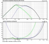
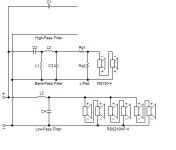
the schematic anD parts values:
3-Way Crossover Network
C2 = 200 µF, Polypropylene, 0.00125 ohms
C3 = 23.22 µF, Polypropylene, 0.00326 ohms
C4 = 400 µF, Polypropylene, 0.000601 ohms
L1 = 8 mH, Air Core(#16), 2.465 ohms
L2 = 2 mH, Air Core(#16), 0.578 ohms
L3 = 6.19 mH, Air Core(#16), 0.916 ohms
BPGain = 2.857 dB
Midrange
L-Pad:
Rp1 = 0.01 ohms
Rp2 = 1000 ohms
JJ
Attachments
I'm sorry but those air core inductors have to change to something else. If you insist on aircore, then they must be 12 gauge or greater. he is talking about having the ability to drive over 1000 watts rms into these speakers, and that will be in the bass area, so those are the parts that, if nothing else, must be best able to handle it. 16 gauge aircore inductors will handle around 3-400 watts rms ok, though really should be used with 2-300 for maximum reliability. I can show some pictures of what happens to 16 gauge inductors when fed by a 350 watt amp capable of huge dynamics way in excess of that.
I also have some 20 gauge inductors which took the brunt of a surge from the power supply caps failing in one of my amps. The amp was only able to do around 150 watts rms, and the power supply caps, while pretty large (47,000uf's), weren't nearly as ridiculous as some setups. The full discharge of that that one cap when it failed fried all of the inductors and caps in the crossover.
I also have some 20 gauge inductors which took the brunt of a surge from the power supply caps failing in one of my amps. The amp was only able to do around 150 watts rms, and the power supply caps, while pretty large (47,000uf's), weren't nearly as ridiculous as some setups. The full discharge of that that one cap when it failed fried all of the inductors and caps in the crossover.
I'm sorry but those air core inductors have to change to something else.
Yes, certainly. Those details were copied straight from crossover pro, I didn't even look that it was specifying an air core inductor. I did look at the cap values, and decided to leave them as PP, since I think you manage that with GK's stated budget. 🙂
I would like to see the pictures of the melted inductors, that would be cool🙂
JJ
BlueWizard said:
Glen, I think you are misunderstanding Sreten. Also, no need to be so defensive; it doesn't hurt to restate your goals, and your goal really were not that clear in your original post. True, they did become clearer as the thread grew, but I didn't understand your underlying purpose until quite a few posts into this thread.
So, my point, restating your goals and purpose in new words now and then doesn't hurt.
Now to the main point, in a round-about way, Sreten is asking what I've been asking (in my own round-about way).
My interpretation is -
"What are you trying to demonstrate?"
"The normal class A quality into a sensible load ?"
To me this is Sreten saying - isn't your real long term goal rock solid unerring fidelity?
"The class AB quality into poor loads ?"
Rather than the arc welder like current sourcing capability?
True, being able to demo low impedance loads proves that the amp is stable and with great capabilities. But again, driving low loads just to be driving low loads is pointless, unless of course you really are designing arc welders.
In daily practice, you want this immense stability and mammoth current sourcing capability to enhance the normal high fidelity listening experience.
So, again, by my interpretation, Sreten is just saying, when it comes to building speakers for this amp, concentrate on quality and fidelity, not on quantity and current demand. Which is exactly what I'm saying. Whatever you decide for speakers should be a decision made to maximum quality of sound, and that in turn, will show off the stability of your amp.
No one is criticizing your Amp. No one is even criticizing your evaluation of varying speaker impedances. We all absolutely agree that this is one fantastic amp. What we are criticizing is your apparent obsession with driving low impedance for the sake of driving low impedance.
Now that you have both Quality and Quantity in your amp, concentrate on pure quality for the speakers, and the resulting impedance will be what ever it will be. Low impedance, in and of itself, shouldn't be a goal, though at times low impedance can be the inevitable and unavoidable result of trying to achieve a particular high fidelity design. But again, it is an unavoidable result, not a goal.
Now that you have this Quality Amp, your goal should be Quality Speakers for the sole purpose of producing the [/i]Highest QUALITY Listening Experience[/i].
The demo of the extreme current sourcing capability of this amp, should be little more that a novelty on the side.
So, once again, low impedance for the sake of low impedance just dumps current down the drain all day long. Yes, without a doubt, it is an important characteristic in an amp, but again, now that you have the amp, your next goal should be the best absolute fidelity in your speakers that is possible within your skill level and budget.
Your amp would do much better to drive an 8 ohms load or a 4 ohms load with unerring fidelity than it would to dump current into a 2 ohm load all day long. Plus, if your resulting speakers are in the 4 ohm or 8 ohm range, that means in the future, for what ever reason, you can still add a second set of speakers and maintain very high fidelity even the resulting low load.
So, once again I ask, do you see my point? Do you see what I am getting at here?
You goal is and always should have been Quality not Quantity. Likely your amp, much to its advantage, has both. But don't compromise the quality of the amp, by misplace objectives in the speakers. Quality of sound and experience should be the first and foremost goal.
Just rambling on.
Steve/bluewizard
Steve, I see your point but I think this discussion is beginning to go round in circles. I’m am definitely not interested in compromising fidelity and acoustic efficiency just for the sake of drawing huge current.
I am also not interested in building a pair of speakers to push the amp to its limit. As I said previously, for this amp, with enough capacity to drive a parallel pair of Apogee speakers connected to each channel (and I am hoping to arrange such a test), a 2-ohm load is still a very light load!
This is what got me thinking along the lines expressed in my opening post – building a speaker with parallel drivers. My reasoning was that if two conventional 4-ohm 4-way speakers could be parallel connected and combined in one box, then bingo, the design goal of an efficient HiFi speaker could be reached with a nominal impedance of 2 ohms.
So, from the following discussion I’ve learnt that the only possible workable arrangement would that shown in my figure “D”, but it would be extremely complicated to pull off successfully. OK, that’s fine – back to the drawing board (please note that I’m not ignoring the advice I am being given!).
Another way to reach my 2-ohm goal would be to build a two pairs of conventional 4-ohm (either 3-way of 4-way) speakers and be done with it, and this is an option I may very well fall back on, but am still partial to reaching my goal with just one pair of boxes!
Ribbon speakers or a high fidelity line array perhaps?
Andy Graddon said:
I agree completely.
But this guy wants to show that his amp can drive high power at low impedance.......for his own reasons which apparently have very little to do with sound quality.
Well no, not really, but back to the topic of crossover component values.
My experience with speaker designing is very limited, but my experience with designing passive filter networks isn’t.
I’ve admittedly looked at only limited number of established designs, but one thing that does strike me is lack of imagination in crossover design, which hasn’t appeared to have deviated that much from design practices that were drawn in the sand 40 or 50 years ago.
Now maybe I’m completely off the plot, but with a line array of, say, multiple 8-ohm woofers, I see no immediate reason why each woofer cannot have its own individual passive LPF comprised of ordinary value components, with the parallel connection of all units being made at the input of each LPF.
Cheers,
Glen
Now maybe I’m completely off the plot, but with a line array of, say, multiple 8-ohm woofers, I see no immediate reason why each woofer cannot have its own individual passive LPF comprised of ordinary value components, with the parallel connection of all units being made at the input of each LPF.
You could do that, but for a given crossover frquency, the size of the inductor is directly proportional to the impedence of the driver. What is 4 mH into 2 ohms becomes 16mH
 into 8 ohms to achieve the same crossover frequency. It might be worth doing, but it is an important point to consider.
JJ
jupiterjune said:
You could do that, but for a given crossover frquency, the size of the inductor is directly proportional to the impedence of the driver. What is 4 mH into 2 ohms becomes 16mH
JJ
OK, but to put some figures to those values, 16mH corners at -3dB with 8 ohms an only 80Hz.
Suppose I built a line array in a 3-way with four 8 ohm woofers to get my desired ~2 ohms nominal input impedance.
Now being a 3-way HiFi system I wouldn't be interested in an 80Hz "sub" woofer corner - maybe 500Hz.
Now the inductance value looks rather manageable (not to mention capacitor values) and with a separate LPF for each woofer, they share the total load current.
Hmmmmmmmmm.........
Cheers,
Glen
G.Kleinschmidt said:
Another way to reach my 2-ohm goal would be to build a two pairs of conventional 4-ohm (either 3-way of 4-way) speakers and be done with it
and this is an option I may very well fall back on

- Status
- Not open for further replies.
- Home
- Loudspeakers
- Multi-Way
- Parallel driver interaction in a 4-way system.