Id like to experiment with parallel 12B4A as a power stage, trying out both SE and PP. So basically SE 2 tubes, PP 4 tubes. What OPT impedances should I use? Also I scanned the site and my schematics for 12B4A parallel flea amps but came up empty, does anyone have a schematic I can use as a starting point? Thx.
12B4a has low 1030Ohm plate resistance, so as SE 4-5k OPT is ideal for it.
If you use it as PSE (selecting equal characteristic tubes -practically one pair from few dozens-), 2k..2k5 OPT is acceptable.
12AU7,12B4A PSE schematic needs finishing!
For PP the double values are OK: 8-10K.
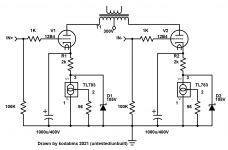
12B4A PP schematic
If you use it as PSE (selecting equal characteristic tubes -practically one pair from few dozens-), 2k..2k5 OPT is acceptable.
12AU7,12B4A PSE schematic needs finishing!
For PP the double values are OK: 8-10K.
12B4A PP schematic
Last edited:
For a triode, max power output would be realized with a primary load (Zpri) of 2*rp.
For PP Class A triodes, each half of the OPT primary would be that 2*rp, so the max power output would be realized with plate-plate primary impedance of 4*rp.
If 12B4A rp = 1.25k, then for SE you'd use 2.5k, and for PP you'd use 5k plate-plate.
If you want less distortion, better damping, but less power output, choose a higher ratio of Zpri/rp. Maybe 3:1 instead of 2:1. Or 4:1 like euro21's suggestion.
The things to figure out are the turns ratio (Tpri:Tsec) and how that defines the impedance ratio (Zpri:Zsec), and the Lpri (primary inductance) which will define the low frequency cutoff.
This is all in RDH4, of course, complete with graphs and equations a-plenty.
radiotron designers handbook - Google Search
If you (also) aim for quality, I doubt the suggested OPT's will deliver.
125E: Frequency response: 150 Hz. - 15 Khz at full rated power (+/- 1db max. ref. 1 Khz). See: https://www.hammfg.com/electronics/transformers/audio/125a-125e.pdf
125ESE: Frequency response: 100 Hz. - 15 Khz at full rated power (+/- 1db max. - ref. 1 Khz). See: https://www.hammfg.com/electronics/transformers/audio/125se.pdf
At full rated power which parallel 12B4 has no hope in hell of achieving... At the power level a pair of 12B4 will make, these parts will be "hi-fi"...
Would be fun to experiment with a headphone amp made with a push pull pair of 12B4A for the outputs. What is the primary inductance of that 125SE?
Could even make it DC-coupled by making a LTP out of the 12B4A's using a CCS from joined cathodes to ground, driving that with a simple common cathode amp stage.
Could even make it DC-coupled by making a LTP out of the 12B4A's using a CCS from joined cathodes to ground, driving that with a simple common cathode amp stage.
Attachments
The primary inductance of the 125ESE is 9.58 H minimum.
The primary inductance of the 125E is 2.99 H.
The primary inductance of the 125E is 2.99 H.
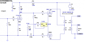
I don't like how close to the limit that TL783 is... Why not offload some of the voltage to a resistor (in series with the cathode and TL783)?
Better yet, give each tube it's own CCS (bypassed with 1000uF) to allow for mismatched tubes?
I added zeners to protect the TL783, and HV caps to protect against a tube failure (arc).
Koda
Better yet, give each tube it's own CCS (bypassed with 1000uF) to allow for mismatched tubes?
I added zeners to protect the TL783, and HV caps to protect against a tube failure (arc).
Koda
Attachments
Last edited:
First off, you can't use a separate CCS for each 12B4A. In this circuit the two 12B4A's are also the phase splitter (it's a long tail pair) so the cathode loads have to have as high impedance to AC signal as possible. Bypassing the cathode loads takes away the AC impedance to the cathodes, so the two 12B4A's will no longer act as a good phase splitter.
As for using the TL783 at all:
R11 1.5k 10W wirewound drops 56V so the TL783 has about 60V across it. It's rated for up to 125V. Or is the problem heat dissipation?
60V * 0.04A = 2.4W
Will require a good heatsink, but would work. OK, but fair point. It's not the best thing to use there. I'll try again.
How about a DN2535 MOSFET CCS? That works. Change R11 to 1.8k 10W so it drops 70V, leaving 50V across the MOSFET which will dissipate less than 2W, which means it will only need a good clip-on heatsink.
Or just replace the whole CCS with a single 3.3k 10W wirewound resistor from the 12B4A cathodes to ground (120V/3300R = 0.036A). THD will be lot higher, but it will be more 2nd harmonic than 3rd.
Attachments

Last edited:
P-P, Hammond 125E
SE, Hammond 125ESE
Thanks PRR, this would be handy and versatile in experimenting.
To be fair, I didn't see the 1k5 resistor at all... My bad.
2.4W isn't too much for the TL783, just use a bolt on heat sink like this: 2pcs/lot Double needle Aluminum Heatsink 38x34x12mm TO 247 TO247 heatsink radiator for MOS,TO 220/TO 3P IC chip heat dissipation|aluminum heatsink|heatsink radiatorheat dissipation - AliExpress
Even better: Aavid Thermalloy 6399B Heat Sink for TO218, TO220 and TO247 3.3degC/W Bolt On Type | Rapid Online
Would be fun to experiment with a headphone amp made with a push pull pair of 12B4A for the outputs. What is the primary inductance of that 125SE?
Could even make it DC-coupled by making a LTP out of the 12B4A's using a CCS from joined cathodes to ground, driving that with a simple common cathode amp stage.
Yes my interest was in a headphone amp / flea amp. Rumors on the Internet often repeat that 12B4A is "like" 2A3, whatever that means. So with my ADHD a statement like that just becomes another shiny object to try out. 😉
Thanks PRR, this would be handy and versatile in experimenting.
As PFL200 points out, this was a stupid idea. Listen to him.
Yes my interest was in a headphone amp / flea amp. Rumors on the Internet often repeat that 12B4A is "like" 2A3, whatever that means. So with my ADHD a statement like that just becomes another shiny object to try out. 😉
LOL, yes, I know the feeling...
12B4A is very different from 2A3. For one thing, max plate dissipation of a 2A3 is 15W, whereas max plate dissipation of 12B4A is only 5.5W. That's a big difference.
However, 12B4A is an interesting little low-mu triode. If you need something like a 6N6P but you really don't need the 15X gain, then the 12B4A can be a handy tool with only about 5X gain. I understand it's not very linear, though.
It sounds pretty much perfect for a cheap 'n cheerful headphone amp project.
There are also lots of threads where people used it to make line level preamps.
Tube DIY Asylum: RE: A high quality(simple) linestage for passive biamping? by Eli Duttman
https://www.diyaudio.com/forums/tub...line-stage-12b4-grounded-grid.html#post771320
...and so on.
Many were happy with it until Salas wrote about a 6V6-Triode preamp, and that one had legs.
6V6 line preamp
Anyhow, this thread is about a headphone amp... I think.
- Home
- Amplifiers
- Tubes / Valves
- Parallel 12B4A ideas