Hi all,
I've done a bit of reading on this topic, but I haven't found an answer yet.
I'm planning to build a parafeed headphone amp with a CCS. What I'm trying to calculate at this point is the load impedance that the tube will see. I think this is going to be determined in part by a combination of the reactance of the parafeed cap and the inductance of the transformer primary. Ignoring ESR and DCR for the moment:
(possibly incorrect?) Assumption: the cap and primary are in series with respect to the tube
Determining this reactance at various frequencies is not tough with the help of Excel. I'm a little stuck as far as how to factor in the impedance reflected through the transformer based on the headphone load though. The reflected impedance would be:
It seems to me that the total impedance that the tube sees is the reflected load (assuming it's static for the moment) in parallel with the frequency dependent reactance of the cap + inductor. Am I on the right track?
Just based on some quick Excel work, and using the assumptions above, I can see clearly why this type of circuit is prone to distortion at lower frequencies.
Bonus stumbling block: the transformer I'd like to try specs the inductance at an unspecified frequency (I'm guessing it's 1k). Is there any way to ballpark inductance at lower frequencies. I'm working at wrapping my head around inductor behavior relative to frequency (inductance would increase at lower frequencies if holding EMF constant, I think).
If anyone can point me to some good discussion or explanation of the parafeed circuit (especially as regards reactance), I'd much appreciate it.
Sodacose
I've done a bit of reading on this topic, but I haven't found an answer yet.
I'm planning to build a parafeed headphone amp with a CCS. What I'm trying to calculate at this point is the load impedance that the tube will see. I think this is going to be determined in part by a combination of the reactance of the parafeed cap and the inductance of the transformer primary. Ignoring ESR and DCR for the moment:
(possibly incorrect?) Assumption: the cap and primary are in series with respect to the tube
total reactance = Xl - Xc
also resonance at f = 1 / (2 * pi * sqrt (L*C))
also resonance at f = 1 / (2 * pi * sqrt (L*C))
Determining this reactance at various frequencies is not tough with the help of Excel. I'm a little stuck as far as how to factor in the impedance reflected through the transformer based on the headphone load though. The reflected impedance would be:
z = headphone impedance * turns ratio^2
It seems to me that the total impedance that the tube sees is the reflected load (assuming it's static for the moment) in parallel with the frequency dependent reactance of the cap + inductor. Am I on the right track?
Just based on some quick Excel work, and using the assumptions above, I can see clearly why this type of circuit is prone to distortion at lower frequencies.
Bonus stumbling block: the transformer I'd like to try specs the inductance at an unspecified frequency (I'm guessing it's 1k). Is there any way to ballpark inductance at lower frequencies. I'm working at wrapping my head around inductor behavior relative to frequency (inductance would increase at lower frequencies if holding EMF constant, I think).
If anyone can point me to some good discussion or explanation of the parafeed circuit (especially as regards reactance), I'd much appreciate it.
Sodacose
Last edited:
The inductance of the primary of the OPT must be as high as possible, in which low frequencies it refers.
Gracias amigo Osvaldo. Yes, I think this is given by:
In this case, Z would be the output impedance of the tube (correct me if I'm wrong).
All things considered, bigger Ls and bigger Cs seem to be the answer but I just want to be sure I understand exactly what is going on in AC terms.
f = Z / 2 * Pi * L
In this case, Z would be the output impedance of the tube (correct me if I'm wrong).
All things considered, bigger Ls and bigger Cs seem to be the answer but I just want to be sure I understand exactly what is going on in AC terms.
Getting there, but not quite yet. The reflected load impedance is in parallel with the transformer primary inductance. In series with this is the transformer leakage inductance and the coupling cap. At low frequencies you can ignore the leakage inductance. At high frequencies you can ignore the coupling cap.Sodacose said:It seems to me that the total impedance that the tube sees is the reflected load (assuming it's static for the moment) in parallel with the frequency dependent reactance of the cap + inductor. Am I on the right track?
Getting there, but not quite yet. The reflected load impedance is in parallel with the transformer primary inductance. In series with this is the transformer leakage inductance and the coupling cap. At low frequencies you can ignore the leakage inductance. At high frequencies you can ignore the coupling cap.
That makes complete sense. Thank you, DF96! I'm not sure why I didn't look at it that way.
Would the resulting total reactance still be calculated by subtracting the capacitive element from the inductive element (ie Xl || Z - Xc)?
use this ... set a very high value for the load inductor
http://www.intactaudio.com/forum/viewtopic.php?t=316
http://www.intactaudio.com/forum/viewtopic.php?t=316
use this ... set a very high value for the load inductor
:: View topic - CL resonant excel calculator.
Hey, that's fantastic! Because I'm using a CCS load, I'm guessing that I can make the plate choke value very high to reflect a very high AC impedance at the plate. I think I read a really good article about the development of this tool at one point, but I couldn't find it again when I looked around.
I'm not quite sure how to correlate the numbers I'm calculating manually in Excel with what the graph shows, but I prefer what the calculator says about frequency response when I input my numbers 🙂
just remember you will need to check with an oscilloscope if the resonance is damped at low freqs and yes make the plate big in the spreadsheet.
that discussion was over the MQ or slage's forum, I can't remember any more. there was a more complex simulator by 'voltsecond' but I believe it was lost when his site closed (thou I might have copies somewhere)
that discussion was over the MQ or slage's forum, I can't remember any more. there was a more complex simulator by 'voltsecond' but I believe it was lost when his site closed (thou I might have copies somewhere)
If you use a parafeed transformer with a high primary inductance (300H and above), the parafeed capacitor (typically 1 to 5 uF) does not play much of a role in the audio band.
However, as GLUCA alteady mentioned, there will be a series resonance circuit formed out of the parafeed capacitor and the primary inductance of the transformer (Fs typically between 1 and 10 Hz). The damping of this circuit will be provided by the internal resistance Rp of the tube.
By adjusting the parafeed capacitor, you can tune the resonance frequecy Fs = 1/ 2*pi*srt(L*C) and the quality factor (damping) of the series resonance Q = sqrt(L/C)/R.
By lowering C, Fs will go up and Q will go down. With a Q below 1 there will be no overshoot or ringing.
Thank you aboos. I'll look at the DCR of the transformer I'd like to use and keep the q point in mind. Just picked up a copy of the Radio Amateurs Handbook the other day actually and was reading about q points.
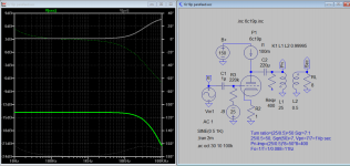
This is my rough calculation result based on the internal resistance of tube going to use. The output transformer will reflect primary impedance equal to internal resistance, and coupling cap is calculated using lowest frequency response, R=400, C=220u,Fo=~10Hz.
Attachments
I think Koonw is referring to the Q calculations (based on the L and C reactance and real world internal resistance of the components).
25H looks low, ungapped transformer for parafeed applications easily have primary inductance higher than 100H; the coupling cap is much lower than 220u, typically 2-6uF will work
Yes, Gluca, 7u and 100H is still good, (only raise the reflect primary impedance of about 5*400=2k, or 5 times). Low internal resistance is an advantage as it's easier to build higher quality opt with lower turn ratio/inductance than a high one. But a coupling cap of 200u is seen here in this sch too, the primary inductance is kept low of 50H, having the low internal resistance of tube in mind and good damping.Read the forum, is here.
Last edited:
the ansa's schematic you linked is not a parallel feeding (those OPTs are gapped) and a good film or paper/oil small value capacitor would sound better than an (oversized) electrolytic capacitor. you want to use a high L ungapped OPT for superior performance, you already have a CCS on the tube and you should be ok with 4-6uF
Damping is also provided by the reflected load. For a pentode this will dominate. For a triode it will still make a difference.aboos said:However, as GLUCA alteady mentioned, there will be a series resonance circuit formed out of the parafeed capacitor and the primary inductance of the transformer (Fs typically between 1 and 10 Hz). The damping of this circuit will be provided by the internal resistance Rp of the tube.
- Status
- Not open for further replies.
- Home
- Amplifiers
- Tubes / Valves
- Parafeed L & C calculations wrt Z?