dont know until i build it..
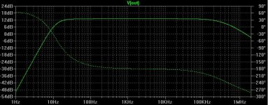
It simulates very much like a choke (a big one at that!) but the proof will be in the making and listening.
You can easily improve the PSRR, just stick a v reg infront of it. I am using the salas hv shunt > CCS (soon to be gyrator) > parafeed edcor.
It simulates very much like a choke (a big one at that!) but the proof will be in the making and listening.
You can easily improve the PSRR, just stick a v reg infront of it. I am using the salas hv shunt > CCS (soon to be gyrator) > parafeed edcor.
How does this gyrator design compare with using a choke load ?
Likely to have better bandwidth at either end, lower output impedance if the Mu output is used, better PSRR, adjustable quiescent voltage if needed....
Member
Joined 2009
Paid Member
Likely to have better bandwidth at either end....
that's entirely possible, unfortunately,I've discovered that 15kHz and above is no longer audible to me😱
that's entirely possible, unfortunately,I've discovered that 15kHz and above is no longer audible to me😱
Yeah, you and me both, darn 357 magnums. I guess we get to save money on output transformers though 🙂...
Athos
Wait - This will limit you to 0.7v on the gates due to the forward voltage....
Edit: Ignore me, back to back is not anti-parallel
The DN2540 is rated for +/- 20V gate-source but at normal operating temperatures saturates at about 0Vgs, so a single 15V zener connected with it's anode to the DN2540 gate (as you would a P-channel) works fine for protection.
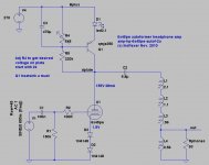
PS Another option for driving headphone or speaker loads is this balanced current totem pole push-pull circuit using a gyrator. The zener is shown as well as a nice cascode.
Another big difference between the Gyrator/CCS and choke or series feed OPT is the need for higher B+ and consequent dissipation in the active load.
Attachments
Last edited:
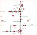
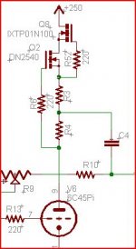
ok here is a cascode version with dn2540. any improvements welcome.
An externally hosted image should be here but it was not working when we last tested it.
Another idea for the gyrator, which I borrowed from Anatoliy. I have built this headphone amp a few days ago and have been listening to it; I think the sound is very good, very dynamic, smooth, no lack of bass, nice full mids. The autoformers I got from a surplus shop for a few dollars. These are the type of line matching transformers used in store ceiling speakers.
I should add that I personally prefer using the mje350, since it's easily available at local shops and can get them easily. I doubt it'd make a difference in sound, when compared to using a dn2540. But that is just a guess.
I should add that I personally prefer using the mje350, since it's easily available at local shops and can get them easily. I doubt it'd make a difference in sound, when compared to using a dn2540. But that is just a guess.
Attachments
Looks fine to me. Since your gate is driven by the plate supply, I think protection diodes aren't necessary. A short from output to ground would be a problem, but that should be easy to avoid.
BTW, with the cascode, a low voltage JFET is an option for the bottom device.
Sheldon
BTW, with the cascode, a low voltage JFET is an option for the bottom device.
Sheldon
Another idea for the gyrator, which I borrowed from Anatoliy. I have built this headphone amp a few days ago and have been listening to it; I think the sound is very good, very dynamic, smooth, no lack of bass, nice full mids. The autoformers I got from a surplus shop for a few dollars. These are the type of line matching transformers used in store ceiling speakers.
I am just this minute drawing up a similar version (but with much smaller cap and a pnp cascode). I'll sim it to make sure no boo boos.
BTW, with the cascode, a low voltage JFET is an option for the bottom device.
Sheldon
Indeed, I have made an excellent CCS using the dn2540 in the upper position, and a 2sk170 in the lower position. For higher current one can either parallel 2sk170s, or use a higher Idss jfet.

With the D3a and a fixed cathode voltage, I'd recommend looking at a CCS version also. With both cathode and plate voltage fixed, the plate current seems to drift around with the D3a. With a CCS the plate voltage only moves a few volts. To me the CCS seems to result in a more consistent op point. Also there's no capacitor to charge and discharge with varying signal levels, were there to be any 2nd harmonic distortion in the circuit.
Some say the gyrator sounds better than the CCS in some circuits, but I'm not getting that impression at all, over a few different amplifiers where I used both and particularly in some recent circuits using the 6C45Pi and the D3a in triode mode. My comparisons are based on using the "mu output" or the center tap, however.
The big difference to me in the gyrator circuit (MOSFET style) is that the resistance between plate and source can be made larger, thus reducing the influence of the MOSFET gfs characteristic. However, the DN2540 has a relatively linear characteristic. I find that the resistance I need to get 10-20 mA current with a DN2540 in CCS mode is enough to get excellent circuit performance.
I agree with Sheldon as long as the capacitor doesn't get charged above the max Vgs there should be little risk. Still, I only omit the diode in the CCS style circuits... I've not yet blown up a MOSFET (in an audio circuit that is...)
Attachments
test bed is complete... just got to get round to pulling the guts out my headamp and sticking this in there
note - the lead length is a bit long on the dn2540s, hopefully i will get away with it but if they oscillate i will whip them out and drill the heatsinks to allow lower mounting.
An externally hosted image should be here but it was not working when we last tested it.
note - the lead length is a bit long on the dn2540s, hopefully i will get away with it but if they oscillate i will whip them out and drill the heatsinks to allow lower mounting.
Last edited:
Hi All
I have a cathode follower and I want to try a gyrator there, i have test it with a N mosfet in mirror drawn circuit,, I am happy to known how the calculations go about this circuit, I want to test it some time in a hybride, the cathode follower has a idle of 20 mA.
Sorry but I have never try a gyrator, i have a CCS loaded one playing in my room.
regards.
test bed is complete... just got to get round to pulling the guts out my headamp and sticking this in there
...snip...
note - the lead length is a bit long on the dn2540s, hopefully i will get away with it but if they oscillate i will whip them out and drill the heatsinks to allow lower mounting.
Try a ferite bead first.
I don't think that gyrator load of cathode follower is a good idea. Better would be stabilize it by bias voltage on control grid, and load on plain CCS.
Hi
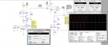
I have made a example what i do, it is a dc coupled hybride.
now I use a CCS for the first and second tube, the sound is hiss to much, the mid is to sharp, feeling of compression of music but this can be the mp3 I did listening to, but resolution of music is exellent, maybe mp3 is much irritant when listening on high end.
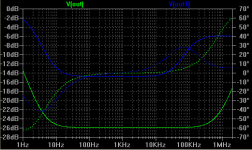
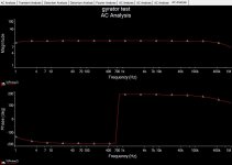
foto 1 is a test and the amp I now listen to is foto 3, 2 is the test measurement in multisim of the gyrator in work incl one for the cathodefollower..
I couple the cathode follower dc to the mosfets with a offset ic control it.
I have change the tube EL84 for 6n6p this tube looks more harsing, sharp mid, with the el84 it is was warmer, maybe because of the double triode being paralell.
How do you calculate the gyrator? for example a 1 mA tube ecc803.
thanks in advance.
I have made a example what i do, it is a dc coupled hybride.
now I use a CCS for the first and second tube, the sound is hiss to much, the mid is to sharp, feeling of compression of music but this can be the mp3 I did listening to, but resolution of music is exellent, maybe mp3 is much irritant when listening on high end.
foto 1 is a test and the amp I now listen to is foto 3, 2 is the test measurement in multisim of the gyrator in work incl one for the cathodefollower..
I couple the cathode follower dc to the mosfets with a offset ic control it.
I have change the tube EL84 for 6n6p this tube looks more harsing, sharp mid, with the el84 it is was warmer, maybe because of the double triode being paralell.
How do you calculate the gyrator? for example a 1 mA tube ecc803.
thanks in advance.
Attachments

Last edited:
I don't think that gyrator load of cathode follower is a good idea. Better would be stabilize it by bias voltage on control grid, and load on plain CCS.
Isn't it the equivalent of fixed grid bias? With a low mu triode like 300B it should be OK...
Hi
I have made a example what i do, it is a dc coupled hybride.
now I use a CCS for the first and second tube, the sound is hiss to much, the mid is to sharp, feeling of compression of music but this can be the mp3 I did listening to, but resolution of music is exellent, maybe mp3 is much irritant when listening on high end.
A properly functioning gyrator doesn't add significant hiss or cause listening fatigue, but those are classic symptoms of RF oscillation.
- Status
- Not open for further replies.
- Home
- Amplifiers
- Tubes / Valves
- parafeed - Gyrator vs CCS anode load