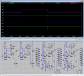
Wow. The simulated waveform is very similar to what i see on the scope. Seems like the simulation predicts something like 4MHz, right?
Looks close to what I see too...
Thanks for the feedback, guys. Though there was a lot of emotions, please believe me that I would like to give a helping hand and such a help should be an engineering analysis as a basis for the issue solution.
Thanks, I will try it/this (and some variations) (this evening) and report back.
Here are some, preliminary, results.
After some experimentation:
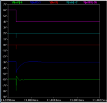
V(tst1) Uncompensated CVS+CCS (left schema)
V(tst2) Compensated CVS+CCS (2nd schema)
V(tst3) Uncompensated CVS+CCS+Shunt (3rd schema)
V(tst4) Compensated CVS+CCS+Shunt (2nd schema)
V(n001) Input voltage.
The V(tst1) track shows some ringing, this may lead to oscillation (especially on a very noisy mains). 1st-ring about 8Mhz 2nd-ring about 4Mhz.
The V(tst2) seems well dampened.
The complete standard Paradise PSU, V(tst3) performs excellent, but one should consider that this is a simulation. Placing real world components on a PCB and connecting an actual power source will have its, negative, influence. The complete compensated Paradise PSU, V(tst4) performs excellent also, the compensation as added in the attached schema, e.g. Cc1=470pF and Cc2=2.7n has no real impact in the functioning of the PSU.
As I’m sure that this is not the final word on compensating (when the PSU oscillates (and if)) we have to wait what kind of results compensation gives on the currently misbehaving PSU’s.
Attachments
Last edited:
OK, now there is a MicroCap and LTSpice simulation result, different simulation software, little bit different excitation voltage and scale of observed voltage plots. To me, based on simulation, the original circuit is only conditionally stable. Now the frequency compensations have to be verified on misbehaving boards.
DL 103
After a few hours of listening and more LPs I changed the load resistance to 1k.
Chris
After some experiments, in my setup 2k works very fine.
After a few hours of listening and more LPs I changed the load resistance to 1k.
Chris
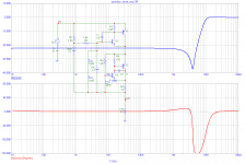
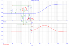
This amplitude and phase response might reveal possible oscillations. Please see circuit without compensation and with 2 compensation capacitors. Caps make the circuit stable, but reduce HF suppression.
Incredibly good response up to 2M in the first (uncompensated) case.
Incredibly good response up to 2M in the first (uncompensated) case.
I know/knew 🙂
This amplitude and phase response might reveal possible oscillations. Please see circuit without compensation and with 2 compensation capacitors. Caps make the circuit stable, but reduce HF suppression.
Yes that is what I said.
... I did/do prefere option 1 as it preserves the speed of the circuit.
Incredibly good response up to 2M in the first (uncompensated) case.
That is where the pre-regulator works, it will stop anything in that range (1M and above) before it enters the CVS/CCS/Servo 🙂
So if we use the prereg, we can be sure to minimize or null any oscilation possibility right ?
Only at your own risk. It is far from clear that the oscillation is initiated by incoming noise.
After a a few experiments all oscillation is dead applying the compensation shown in post #983 with both comp caps at 2200p.
The compensation scheme shown in post #985 did not work for me.
Good work guys 🙂
The compensation scheme shown in post #985 did not work for me.
Good work guys 🙂
That is where the pre-regulator works, it will stop anything in that range (1M and above) before it enters the CVS/CCS/Servo 🙂
A small correction, 1M and below 😉
It is far from clear that the oscillation is initiated by incoming noise.
You are correct. The original (uncompensated) circuit is NOT stable or is only conditionally stable. This we can see from Bode plots. Yes, after compensation of local feedback loops it gets stable.
So if we use the prereg, we can be sure to minimize or null any oscilation possibility right ?
No, that is not what I said 🙂 Using the prereg removes one possible source of 'agitation' that may start oscillations. The most common source of 'agitation' is the internal noise of the (any) circuit and that cannot be removed.
But, if your PSU is not oscillating (as most) then there is no need to compensate.
BTW this (self-agitation by internal noise) is a good argument to use high quality, low noise, components in every/any circuit. Some times (but not all times) you can spot problems by running the simulation in high resolution (10nS or smaller step size) with no AC signal sources attached. If you look at the FFT of this analysis you may be able to spot potential problems.
After a a few experiments all oscillation is dead applying the compensation shown in post #983 with both comp caps at 2200p.
The compensation scheme shown in post #985 did not work for me.
Good work guys 🙂
That is cool 🙂
In case anyone remembers my old complains that the Paradise will burst into oscillation when shorting the input, or at least something resembling oscillation - this is now completely gone. Apparently shorting the input was feeding ground noise, i.e. the now missing 7MHz into the inputs.
A small correction, 1M and below 😉
I think that the CLC-circuit should be able to stop a bit more (above 1M), but that will depend on the quality (and type) of L being used. There is good cause here to include some ferrite beads in the prereg to stop even higher frequencies (Holger? 🙂).
- Home
- Source & Line
- Analogue Source
- Paradise Builders