I finished the psu a few hours ago, but a litte hang over from last evening (to many cuba libre😎) forced small sound levels 🙄
More reporting the next days.
Chris
More reporting the next days.
Chris
Italy, I know what you are thinking RIAA Preamplifier - a set on Flickr 🙂
Fine! Similar basis, i take this: modu
Splendid build Chris
Congrats.
thanks!
Chris
Looking at Take5's build the only differences i can spot are the substitution of the 6800uf/10v caps and the K170 fets. Otherwise it looks pretty much like mine.
Take5, how is your offset?
Take5, how is your offset?
Not that it appears very important, but does anyone have a theory what could possibly have caused the ground loop in his single transformer build?
Not that it appears very important, but does anyone have a theory what could possibly have caused the ground loop in his single transformer build?
Have a look at Mpp#7635 and more. Also Mpp#7733 and more. I think to remember that there are some pointers there.
These are the most important/relevant messages regarding PSU and Pre-Reg.
- Mpp #4375 PSU-pre-regulator.
- Mpp #4610 V2 Schemas UPS and Amp.
- Mpp #6506 CCS fine-tuning.
- Mpp #6462 PSU with my notes.
- Mpp #6809 Do not try to feed the CVS of the CCS of the shunt with a regulated power supply.
- Mpp #7127 More about transformer selection.
- Mpp #7635 Single and dual transformer wiring (also corrected drawing) (See also #7733).
- Mpp #7733 Grounding (PSU, RIAA and Player).
- Mpp #7810 35V PSU for the CroMagnon.
- Mpp #7830 The PSU explained.
- PradiseBuilders #155 Vdc input voltage minimum simulated.
Also, if you ever want to know what was removed at that time:
===Removed=== Mpp #7633 FdW
Yes I know that.... I am actually using only one pre-regulator feeding the
two boards and have been using that setup in other situations (my power amp for instance) but
would like to profit from some better crosstalk isolation. The trouble is I am actualy working
on a very tight budget and can not get another TX in the near future so I found this idea in
the ESP pages.... Power Supply for Power Amplifiers
What bothers me more is that I can not identify the extra GND loop when going from one single prereg
to two preregs in parallel using the same TX.
A picture tells more than a thousand words (I hope). With the shared power supply, and a record
player that connects the 2 signal returns to each other or/and to ground (dotted lines), you
have the ground loop indicated by ABCD.
===Removed=== Mpp #7634 FdW
> Quote:7633 FdW
Updated single transformer ground wiring and subsystem connections (see attached drawing).
See also Mpp #7628
And Mpp #7630
And Mpp #7633
And http://sound.westhost.com/project04.htm sound.westhost.com project04
These are the most important/relevant messages regarding PSU and Pre-Reg.
Mpp - Post 4375 PSU-pre-regulator
Mpp - Post 4610 V2 Schemas UPS and Amp
Mpp - Post 6506 CCS fine-tuning
Mpp - Post 6462 PSU with my notes
Mpp - Post 6809 Do not try to feed the CVS of the CCS of the shunt with a regulated power supply
Mpp - Post 7127 More about transformer selection
Mpp - Post 7634 Single transformer wiring
PradiseBuilders - Post 155 Vdc input voltage minimum simulated
Have a look at these and their following messages.
===Removed=== Mpp #7635 RCruz
Thank you Frans... but that issue also appears when using a single TX nd single prereg does it not ?
I post a corrected image with the TX connections I want to use:
7636 FdW
> Quote:7635 RCruz
Yes it does the only way to get rid of these loops is using 2 TX's. And yes you can use those
connections. I also updated the drawing; it now includes a diagram for the two TX grounding.
===Removed=== Mpp #7638 FdW
Just to make it clear I am using a single TX with single prereg without any hum.
I removed some components so you can view easily what I mean.... the two pics below represent the
single prereg that I am using now (perfect) and the new layout I would like to try.
Please let me know if you see an aditional GND Loop in the double prallel prereg sketch 🙂
> Quote:7639 RCruz
If there is no hum in the first then I see no reason for hum in the second. Beyond that, check
the player for the Q1, Q2 and Q3 connections.
===Removed=== Mpp #7639 RCruz
I do not have connections Q2 or Q3 in my build... that is why I do not have hum with a single TX.
===Removed=== Mpp #7640 RCruz
BTW.... I am having difficulties figuring how your single TX schematic works.... there is no
centre tap in L1 or L2 ???
===Removed=== Mpp #7641 FdW
> Quote:7639 RCruz
Q1, Q2 and Q3 are in the player (possibly)
===Removed=== Mpp #7642 FdW
> Quote:7640 RCruz
You found a bug and I fixed it [It seems that I am not capable of doing something right the
first time ].
===Removed=== Mpp #7643 RCruz
Thank you so much Frans..... I am relieved you do not see any additional GND loop by paralleling
two preregs after the single TX secondary.
I will try this arrangement and upgrade to dual TX when I get some spare t$me
===Removed=== Mpp #7644 FdW
> Quote:7642 FdW
It would be good (for me at the least) to get some input/reflection/critique on this drawing, it
may be referenced frequently (by the builders) and I want it (and it’s remarks/assumptions
(riaa’s and record players is not my daily thing )) to be correct.
So if you have any remarks/input regarding this... don't be shy See Mpp #7642
===Removed=== Mpp #7645 RCruz
Just one more question Frans, in your double mono schematic (two tx) I see you do not connect
both grounds (left and right) together.
Also you do not make any reference to the output connections, so I admit we can leave both
channels running completely independent without any common reference between them. What if
there is a slight voltage difference between both channels grounds... does it procuce a current
flowing in the output interconnects ? (I assume both output negatives will be joined inside the
following preamp / power amp).
===Removed=== Mpp #7646 RCruz
OK.. now I perfectly understand both circuits. The second is perfect and the first one I will
build and report back.
Regarding TT connections, IMO Q2 and Q3 are not common because in good setups, the four wires
comming out of the cart are always isolated from each other.
Connection Q1 to C is normal if C is the tonearm tubing, but C does never connect to any wire
comming out of the cart.
That is why a single TX + prereg works.
PS:
Please let me know your opinion on: Mpp #7645
===Removed=== Mpp #7647 FdW
> Quote:7645 RCruz
That’s right (spotted) and it is wrong (drawn). Check this out here is an updated (again) drawing
In this new arrangement for 2 TX's the circuit/signal-ground is only connected (left to right) in
the attached amplifier, no loops possible any ware. Your concern about voltage differences is
cared for by the RX, RXL and RXR resistors.
Wow this is difficult to get right... but we will succeed
===Removed=== Mpp #7648 FdW
> Quote:7646 RCruz
But no harm in checking I will leave the notes about it in the drawing.
===Removed=== Mpp #7649 RCruz
Now it looks cool.... wonderfull idea those 10 ohm resistors to take care of gnd voltage fluctuations...
I am really glad you cared to hep me in this subject.
Now about chassis grounding and TT ground connection.... My best results where obtained by connecting
the chassis directly to mains earth and connect the circuit gnd to the chassis via the DDCR.
So A2, E2 and G should be all connected together forming a star but isolated from the chassis. The
TT arm GND wire should then be connected to this star gnd and not to the chassis.
Please take your time to review this because these are my findings... not a rule
===Removed=== Mpp #7650 Joachim Gerhard
This is an interesting discussion, thanks.
===Removed=== Mpp #7651 RCruz
Please reread #7649 after my last edit
===Removed=== Mpp === That's all 🙂
Last edited:
I see what you mean - it's just common sense and general grounding guidelines. It is, as i suspected, irrelevant to the issues some of us have. Thanks for the detailed reply.
Take5, how is your offset?
Output Offset, 5mV adjustment on my very old scope:
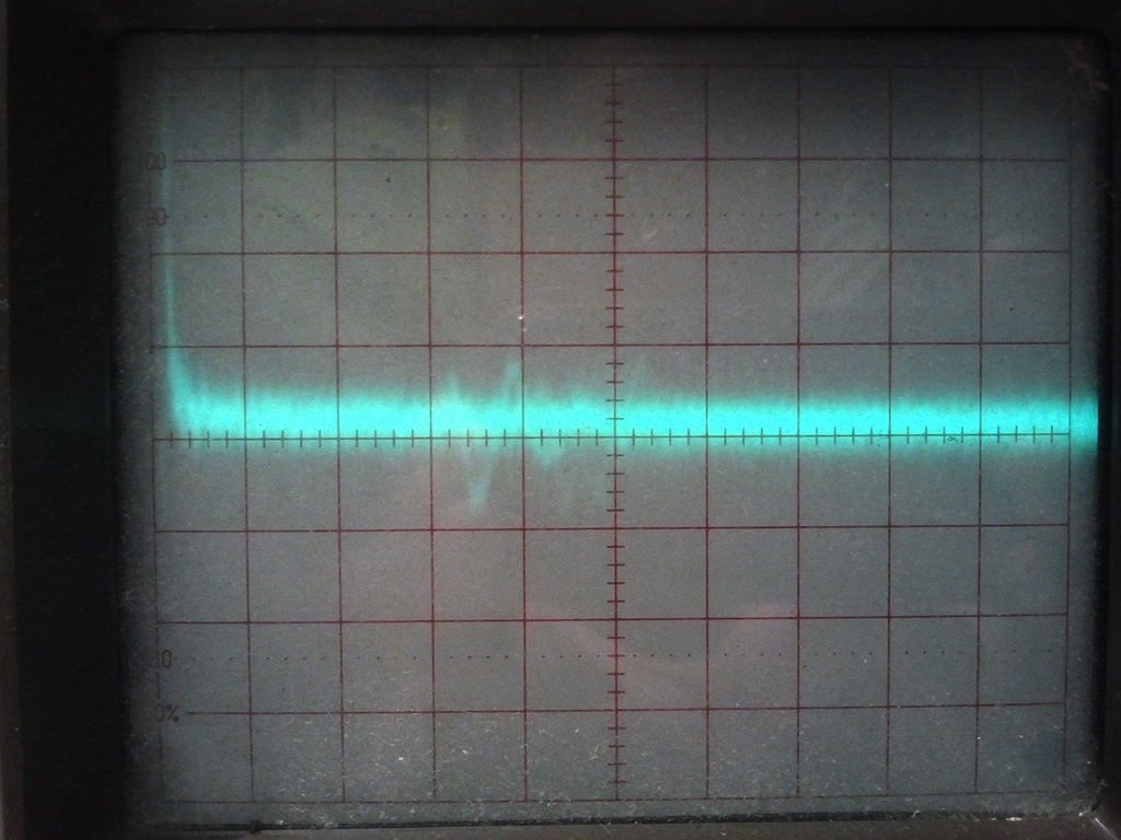
Chris
Last edited:
Could you just take a reading with a DVM? Does the oscillogram indicate a couple mV of white noise?
Could you just take a reading with a DVM?
DC is floating between +30 / -30 mV.
Does the oscillogram indicate a couple mV of white noise?
Yes
Thank you. My measurements under the same conditions appear a bit worse, but not by orders of magnitude. Hiss levels with a 103 also appear intolerable.
If this is indeed normal operation, then this device cannot safely be used in a dc coupled system. There should be a coupling cap somewhere and probably best ahead of the buffer in order to minimise its value. Maybe Joachim can suggest an appropriate spot for a cap.
If this is indeed normal operation, then this device cannot safely be used in a dc coupled system. There should be a coupling cap somewhere and probably best ahead of the buffer in order to minimise its value. Maybe Joachim can suggest an appropriate spot for a cap.
DC is floating between +30 / -30 mV.
I need to drag the boards back from the cupboard and measure again, but i think mine measured a rapidly fluctuating dc within 120mV. Could it be your results are better as your input caps are 2 x 4700 as opposed to mine 2 x 6800? I seem to recall Joachim mentioning something along these lines. Maybe further reducing these caps and speeding up the servo will bring some improvement.
Any possibility to improve the stability of the front end?
PMA, what do you think?
Last edited:
Hi,
could one of those in the know (Joachim perhaps) please sum up the latest consensus on optimal hFe?
should i really use the same high hfe throughout the whole board? in the assempby guide input and three other sections are circled in. joachim stated someplace that 400 is enough for the input, but i canot find references to the other sections. there are over a thousand posts in the relevant threads, i`m lost.
i have most matches in the 470-500 range, so if thats fine i stuff with these. (i have a lot of high gain npn, just post me and i may even send some to somebody needing 😀 )
If you have oscillation did you use the 2sk170's or the 107's ?
Could it be an unforeseen issue with the substitution of these parts? I used the 107's and have the oscillation.
Any advice re grade of 2sk170's to purchase I'll try swapping them out?
Could it be an unforeseen issue with the substitution of these parts? I used the 107's and have the oscillation.
Any advice re grade of 2sk170's to purchase I'll try swapping them out?
- Home
- Source & Line
- Analogue Source
- Paradise Builders