Hello Alfred,
your tip with the 50k resistors worked perfectly!!!! 😀
I worked with 100k, and this works good. Now I have some mV on the outputs, All good again.
Now the Calvin buffers are going in 🙂
Thanx a lot, all the people here!
Alfred, you get a PM from me because of the shunt reg....
Remco
your tip with the 50k resistors worked perfectly!!!! 😀
I worked with 100k, and this works good. Now I have some mV on the outputs, All good again.
Now the Calvin buffers are going in 🙂
Thanx a lot, all the people here!
Alfred, you get a PM from me because of the shunt reg....
Remco
Yeah Joachim, i'm very happy!
Now everything is back to normal, and the Calvin buffer is installed.
I really like it, the sound is warmer, has more power in the lower octave. And I hear much more depth.
Keep up the good work, I will build a Calvin Preamp with the new Shunt Regulators from Hesener. Good timing 🙂
And besides that, brainstorming about a new Tube Amp with a GM70 single endet 🙂
Happy listening!
Hi Alfred. Is that that Paradise next to the TT?. My Paradise is doing great guns. The Calvin buffer is improving the dynamics and of course it is so quiet that you can hear every nuiance of the recordings😀.
yes, the big box right next to it. Here is a picture of the front plate, made by schaeffer-ag.de
glad to hear you are up and running, appreciate the sound comments!
Attachments

Hello Alfred,
your tip with the 50k resistors worked perfectly!!!! 😀
I worked with 100k, and this works good. Now I have some mV on the outputs, All good again.
Now the Calvin buffers are going in 🙂
Thanx a lot, all the people here!
Alfred, you get a PM from me because of the shunt reg....
Remco
cool,many thanks for the update! glad it worked....
Thanks, John !
After a short visit in cold New York we are back home.
well you should have come here to Milwaukee...if you think that NYC was cold I can imagine what you would think about this weather....ahahahah!!!!
well you should have come here to Milwaukee...if you think that NYC was cold I can imagine what you would think about this weather....ahahahah!!!!
Nice to see you are still there stefanoo
There... in diyaudio 🙂
ahahaha I could have been dead but still have been on dyaudio...but...yeah I am still on dyaudio and alive!! 😀
😎
Motoring well as a VPI.🙂
yep, you got it 😉
Everybody is invited to the motor party!! ahahahah
I posted a couple of questions in the GB thread for the Paradise Audio, nevertheless there have been no replies, so I´ll give this thread a try:
I have a couple more questions.
1.- As I commented before C91 and C92 are on the Amplifier Schematic but not on any BOM, why ?¿?
2.- C6, C7, C8, C9, C10, C11 on the PDF BOM are not on the Amplifier Schematic, ?¿?¿?
3.- C4a, C4b, C3a, C3b appear as SMD on PDF BOM, but as through hole on Mouser BOM, which is correct ?¿?
4.- C6a, C6b, C7a, C7b same thing.
5.- R104b, R204b are on the Regulator Schematic and show 1M Ohm, and on the PDF BOM no value, not on Mouser BOM.
6.- RIAA Caps not on Mouser BOM (Answered !!!!!)
7.- 470 pF Cap on Mouser BOM not on any Schematic.
8.- 2700 pF cap on Mouser BOM not on any Schematic.
9.- 1 Ohm resistor on Mouser BOM, not on any Schematic.
Not trying to be a pain here just questions regarding what parts should be bought or not.
Maybe there have been changes to the board that are not reflected in the schematics.
By the way, has anyone tried a different RIAA setup ?? Such as the Cruz or Salas instead of the Gerhard Borresen one ?? Any comments on sound any comparisons ?? Any curves detailing the differences, or if someone could explain the differences, it would be greatly appreciated.
Anyway, thanks,
Manolo
Sooo.. first board up and running.. i think everything seems fine except for the calvin buffers...
I run R6/R11 = 4.7R, R5/R7 = 6.8R,
And over R6/R11 i measure ~25mV and over R5/R11 0mV?!? Shouldn't they be the same - since they are tecnically in series? The 2SA1930 sinks doesn't even get hot...
The J107/PF5102 are put in the right way - i have double checked.
In-Out measurement is moving all the time...
The R4/R10 gate stoppers are only 100R - but that shoudln't be any trouble?
The J107 S-D was approx 14.8V, and the PF5102 was approx 2.6V if i remember right.. on both sides..
So what could my problem be? seems like something is strange with the 2SA1930s, but what?
Is the 4.7R's the problem - i got them from Calvins recommendation a few pages back...
Last edited:
I posted a couple of questions in the GB thread for the Paradise Audio,
By the way, has anyone tried a different RIAA setup ?? Such as the Cruz or Salas instead of the Gerhard Borresen one ?? Any comments on sound any comparisons ?? Any curves detailing the differences, or if someone could explain the differences, it would be greatly appreciated.
Anyway, thanks,
Manolo
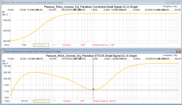
The stock riaa values proposed on the building pdf provide a more dramatic sound presentation with a slight recessed midband (-0.3dB at 1kHz) and a more present high band. It suits the majority of the systems.
My interpretation of the riaa values tend to give a more uniform eq and so the sound is somehow leaner.
A question of taste.
Please take the images with a bit of salt as these are purely simulations so the bass rollof you see here is not real.
Attachments
Anyway, getting the straight line response riaa filter is not so important as matching between channels.
Both riaa filters must match really close otherwise you will compromise the very important gain / phase relationship between channels and corrupt the precious stereo image.
Both riaa filters must match really close otherwise you will compromise the very important gain / phase relationship between channels and corrupt the precious stereo image.
Attachments
Hi,
@Rolle2k
I´d say take a look at the datasheet for the transistors pinouts 🙄
Seems that SA1930 and SA1381 pinouts differ!
Lucky You that You just need to turn around the 1930.
In my sims the SA1930 adds some THD, but that may be a problem of the used models.
With the wrong orientation there should be noticeable Base current through the bipolars into R4 and R10 (which at the same is close to the transistors collector current here, leaving only a tiny emitter current left contributing to R6/11s voltage drop).
My sims show a voltage drop of ~40mV over R4 and R10.
With the right orientation of the bipolars the typical base current <<1mA flows resulting in <10mV of drop over R4/10.
note: always check parts pinouts, even if it is the same part from a different manufacturer.
The 5551/5401 transistors often used in power amp input stages are a prime example.
jauu
Calvin
Last edited:
- Home
- Source & Line
- Analogue Source
- Paradise Builders