Turntable with this motor stopped working. Here is a brief description of electronics:
- electronics are fed by an external 24VDC power supply (working)
- 7824 regulator feeds the motor and the subsequent regulator 7805
- 7805 feeds the microcontroller and gives the logical +5V voltage to turning direction pins on the motor
- external microcontroller is P87LPC767
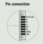
Beside these components which are on external PCB, the motor itself has Hall generator and other electronics integrated. Here are the connections to the motor:
ACTUAL - FG output (not connected)
A/B - direction control inputs (A=+5V, B=GND > clockwise direction)
S+ - speed control voltage (0-10VDC, currently 2.5VDC)
S- GND
GND
UB - motor supply voltage (23VDC)
All regulated voltages are OK.
The motor datasheet can be found here:
https://www.google.com/url?sa=t&rct...p?pID=142159&usg=AOvVaw18Soh8ZFbFqqJ0_aNrisnl
The first thing to note is that the external microcontroller doesn't have any speed feedback from the motor. It turns out that the entire role of P87LPC767 with its external quartz crystal is to maintain a steady reference voltage.
Does anyone have any experience with repairing this motor? Thanks in advance.
- electronics are fed by an external 24VDC power supply (working)
- 7824 regulator feeds the motor and the subsequent regulator 7805
- 7805 feeds the microcontroller and gives the logical +5V voltage to turning direction pins on the motor
- external microcontroller is P87LPC767
Beside these components which are on external PCB, the motor itself has Hall generator and other electronics integrated. Here are the connections to the motor:
ACTUAL - FG output (not connected)
A/B - direction control inputs (A=+5V, B=GND > clockwise direction)
S+ - speed control voltage (0-10VDC, currently 2.5VDC)
S- GND
GND
UB - motor supply voltage (23VDC)
All regulated voltages are OK.
The motor datasheet can be found here:
https://www.google.com/url?sa=t&rct...p?pID=142159&usg=AOvVaw18Soh8ZFbFqqJ0_aNrisnl
The first thing to note is that the external microcontroller doesn't have any speed feedback from the motor. It turns out that the entire role of P87LPC767 with its external quartz crystal is to maintain a steady reference voltage.
Does anyone have any experience with repairing this motor? Thanks in advance.
Attachments
If its the motor and not the control electronics then you need a replacement motor. Origin Live in the UK and Oracle audio in Canada have replacements for one or two Pabst motors , but it was a common failure for 1980s turntables and Pabst stopped making them. So if its an expensive turntable the Origion motor may work, but its expensive.
Thank you for your reply. The motor in question is MB Papst from 2009 and is still in production. Beside the external electronics, the motor itself has internal electronics and I'm still not in, so wanted to check what to usually expect when this motor stops working.
The motor is definitely dead. I fed 24VDC to supply pin and 5VDC to speed control pin (which is 50% of speed control voltage range) and it doesn't react. When connected to power supply, the motor enters brake mode, that is, it resists shaft movement, so there is definitely fault in the motor.
Exploring further the external electronics, the speed control voltage is regulated from P87LPC767 microprocessor, pin 12. There is 2.6VDC coming from there, but there is also an AC component of the same voltage. Since I currently don't have an oscilloscope with me, I cannot see what is the signal form. I was trying to understand it from the microprocessor datasheet, which can be found here:
https://www.google.com/url?sa=t&rct...pc767_ds.pdf&usg=AOvVaw0EX63nPaiqLgUqadGhuVk8
What is the expected signal form on pin 12, anyone? Thanks again.