I have a question about the Papst external rotor type motor operating in a Fairchild 412-1. I can get it to work very well at 60 Hz and 110VAC. But the problem arises when I try to increase the turntable speed to 45 rpm by increasing frequency.
I've been an avid follower of the threads about motor controllers. Several years ago I used the SG-4 generator to drive a Papst external rotor type motor. I did this relying heavily on suggestions in a couple of the SG4 threads (especially comments from @ralphfcooke ) and operate it as a 3 phase with no run capacitor. That project powered an Empire 208 and it has worked perfectly for several years.
I'm currently working on a Fairchild 412 that has the same motor. In this case I thought I'd just leave the run capacitor installed and create a simpler controller that just outputs line voltage and let the run capacitor create the 3rd phase. This setup works fine at 33 rpm, operating at 110VAC and about 60Hz. The problem arises when I try to increase the frequency for 45 rpm operation. The 412 is a single speed machine (i.e. no mechanical speed changer). If I increase the frequency to about 81.8 Hz, the motor slows noticeably and eventually stalls. I am wondering if this is caused by the amount of phase shift from the capacitor being impacted at a different line frequency (I believe phase shift is frequency dependent). I can get it to operate properly at 81.8Hz if I increase the voltage to about 139VAC. However I worry about operating the motor at substantially higher voltage than its rating.
I would great appreciate thoughts about this situation. Will this simple approach work or do I need to go to full 3 phase operation?
Thanks.
Most small motors are designed to price.
Helix angle of rotor, winding and so on are important.
Some designs do well with variable frequency drives, most do not.
Options:
1. Find another turntable if you really want lo listen to 45 rpm recordings.
2. Make another set of pulleys.
Both are safer and more durable solutions, and effective compared to drives. Small drives are rarely as well made as bigger ones.
The capacitor solution for three phase is used only to check motors after rewinding, or before that, when a three phase supply is not available, only single phase is available.
Not during runs.
That is a makeshift solution, it appears you are using a single phase motor as a three phase motor.
A better solution would be to obtain a three phase motor, difficult below 1/4 HP here, and use it, which means you need a three phase supply.
Best solution would be to go solid state, in my opinion.
Just store the music on hard disks or USB sticks, enjoy.
Last edited:
The Pabst in a Fairchild is not "designed to price".
You want to change the cap to 0.74 of value, and yes you want to up the voltage by 1.35. You are not overvolting because this is an inductance. Yes if you went over 1,000V you could have arcing but 150V is not going to bother the lacquer or paper insulations.
You want to change the cap to 0.74 of value, and yes you want to up the voltage by 1.35. You are not overvolting because this is an inductance. Yes if you went over 1,000V you could have arcing but 150V is not going to bother the lacquer or paper insulations.

Constant V/F= V1/F1 =V2/F2....is the principle of frequency drive so for constant torque you change both voltage and frequency and keep the same ratio you have at 110v/ 60hz thus at 81.8Hz you should have 150V AC but you don't really need going that high to achievecenough torque. The usual motor impregnating lacquer in Europe allow motors to go safely at 400Hz while the mains 3 phase voltage is 50hz/380V so at 400hz should theoretically have over 3000v, but the transistors used in usual vfd drive are specd at max 1200V so they won't probably go over 600V.Anyway 150V is nothing....I can get it to operate properly at 81.8Hz if I increase the voltage to about 139VAC. However I worry about operating the motor at substantially higher voltage than its rating.
Thanks.
Last edited:
If you use the SG4 to drive it as a 3 phase motor, you will have 0°, 120° and 240° going to the motor. With a cap, you have 0°, ~80° and 180° so the motor will be very inefficient and have little torque. With the SG4 3 phase drive, you can probably lower the voltage for both 33 and 45 RPM, but you will need higher voltage at 45 RPM because the motor produces higher back EMF at higher speeds which reduces the current consumption and torque is proportional to current.
Get a Kill-A-Watt meter at Home Depot (or equivalent) and monitor the power consumption going into the amp driving the motor. Adjust the output voltage to keep the input power consumption constant at both speeds. The power going to the motor will be approximately the input power x amp efficiency.
Get a Kill-A-Watt meter at Home Depot (or equivalent) and monitor the power consumption going into the amp driving the motor. Adjust the output voltage to keep the input power consumption constant at both speeds. The power going to the motor will be approximately the input power x amp efficiency.
Thanks for all the great information. This is what I love about this hobby - people willing to provide knowledge. The learning is as much fun as the building.
Bill, I have used your SG4 to drive a similar motor as 3 phase a few years ago and it worked great but I only used it at 33 rpm. I know the SG4 can have different voltages at different frequencies.
Bill, I have used your SG4 to drive a similar motor as 3 phase a few years ago and it worked great but I only used it at 33 rpm. I know the SG4 can have different voltages at different frequencies.
I'm lead to believe that some papst aussenlaufers are specified to run at a certain frequency, voltage and speed by employing asymmetric windings. I can't imaging they'd be able to shift the position of the windings/poles to compensate for a suboptimal phase difference, so this must use unequal winding counts. This implies that if you are trying to minimise noise, an equal voltage on each winding may not be optimal. If anyone has more info, i'm all ears...
A single phase motor of that type is like a ceiling fan, and the three wires there are Start and Run windings, with a start / run capacitor. One wire is common, should go to Live or Neutral as per diagram.
The resistance is different between the two windings.
The coils are not the same size, in terms of length and position with respect to the center.
Some OCD motor maker even use different diameter wires for the start and run windings....
Running such a motor on three phases, with essentially unbalanced windings, is very politely, injudicious.
It would be a better idea to use a single phase variable speed, drive with low noise....a big honking rheostat connected to 220V on primary, secondary to motor!
It would be an even better idea to buy another table...with 45 built in.
Also, like mentioned in above post, the windings are designed with a particular purpose in mind.
And like I said, all motors do not take kindly to being driven with different frequencies.
Helix angle of rotor and stator, magnetic properties, air gap, and many other factors go into making a good motor.
There must be more information on line, if you are curious.
Last edited:
Naresh, I have more than a dozen Papst 3 wire motors, and, without exception they all have the same resistance between any two wires.
Some are synchronous with a 'steel' section in the rotor, others have soft iron and are asynchronous. If you have the Papst codes, numbers beginning with 901 are synchronous, 902 are not. After testing several of my '902' motors it appears that the retentivity of the rotors vary, allowing some motors to be closer to synchronous than others.
I do also have one 'odd' Papst motor, with different resistances between wires, but this is definitely a fan motor and has 10 wires.
I am not claiming that Papst have never made a 3 wire motor with separate start and run windings, but I haven't yet come across one.
Attachments
I am not so good in German, it seems single phase motors with capacitor, and three phase standard motors were both available from the maker in the same style of housing.
The graphs indicate a drop in torque near maximum speed....so if you cross maximum speed, there is a sharp drop in torque.
The graphs do not tell us what happens when you take a 1500 rpm / 33 1/3 rpm drive unit, and run it at 2027 rpm / 45 rpm...
There seems to be a sharp drop in torque at speeds nearing 1500 rpm.
Extrapolating that to 2000 rpm odd means negligible torque, may not drive the table properly...
Like I said, go digital, or buy another table with 45 rpm facility.
Hi Naresh,
You're reading the data incorrectly, the motors cannot exceed synchronous speed at any excitation frequency, that would
disobey the laws of physics.
As Bill (Pyramid) said above, when you feed the motor with a higher frequency the increased reactance means
less power will be drawn for a given supply voltage, therefore you need to increase the voltage and reduce the capacitance when feeding
from a single phase supply.
All of my Papst motors have equal resistance between windings and will run perfectly on a 3 phase supply, indeed they will provide more torque at lower supply voltage, with significantly less vibration. When powered by the SG4 it is quite easy to adjust the output to the point where is is very difficult to tell whether the motor is running when holding it in your hand.
I appreciate that there are many types of motor, but the vast majority of these 3 wire Außenläufermotor
are delta wound 3 phase motors, which can be operated on single phase with a phase capacitor.
I did say my German is poor.
There are some torque curves and connection diagrams later in the pdf, and it was unclear to me, it seems the same motors are sold as single and three phase.
Now you say the motors have a symmetrical winding which allows single OR three phase supply to the same motor.
Quite unusual, really.
Thanks for telling me.
To slightly correct what Ralph said, the reactance of the windings does increase with frequency, but not significantly as the power factor is fairly high and the load is mostly resistive. What does increase to a greater degree is the back EMF generated by the magnetized rotor spinning within the stator windings which is proportional to speed. The motor acts as a generator and a motor at the same time. Most motor mfrs will have a spec for BEMF expressed in V/Krpm.
The back EMF generated opposes the driving current which essentially increases the impedance of the windings so less current is consumed and less torque is produced. If you continued to increase the speed (frequency) without changing the drive voltage, the back EMF starts to approach the applied voltage and at some point the current draw (and torque) will drop so low, the motor will stall. Conversely, if you start the motor at a slower speed, you need to reduce the voltage as there is less back EMF generated.
When you raise the voltage with speed to compensate for the back EMF, you must be careful not to stall the motor at high speeds as the current draw will be excessive with higher voltage and zero back EMF at that point.
I've designed a HV supply for a high end table mfr who uses the 901 8032 006 motor in a turntable application with a 200 pound platter and it starts the platter at ~5 RPM and ramps up to 33/45/78 RPM while maintaining constant power consumption no matter what speed it is spinning. The voltage to the motor at 33 RPM is ~50VAC and 115VAC at 78 RPM. Because of the range of frequencies, we could not use step up transformers so it has a directly coupled 3 channel HV amp running from ±170VDC rails.
Dear All,
I want to use a Past motor for my DIY turntable.
I saw that this was solved here. I would be interested if you could send me your wiring diagram
Andrew
I want to use a Past motor for my DIY turntable.
I saw that this was solved here. I would be interested if you could send me your wiring diagram
Andrew
Attachments

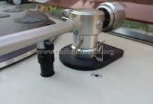
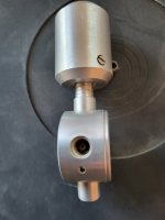
The Papst motor you show is not ideal, being a reel rather than a capstan motor. There are two major differences that I'm aware of; reel motors are designed to run at very different speeds instead of the constant speed of a synchronous motor; and most have ball race bearings which are rather noisier than the sleeve bearings used in capstan motors.
With Papst motors the OEM number gives a good indication of the type; numbers starting with 901 are synchronous, 902 are near to synchronous but do adjust speed a little with load; and 903, which are designed to vary in speed with load and voltage.
With Papst motors the OEM number gives a good indication of the type; numbers starting with 901 are synchronous, 902 are near to synchronous but do adjust speed a little with load; and 903, which are designed to vary in speed with load and voltage.
Dar Ralph,
)
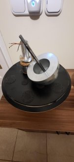
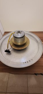
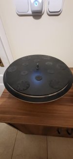
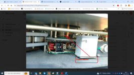
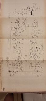
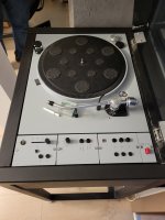
Between 1980 and 1992, the Mechlabor SL 102 record player shown in the picture was driven by the Papst motor shown in the picture and the controller shown in the drawing.
I would like to make a copy of this record player that still works today. I would like to make speed control and display in a more modern design.
The motor is incredibly quiet because the ball bearing has been replaced with a sinter brass bearing. The shaft run out is less than 0.001 mm.
Bearing gap 0.002mm. So the mechanics are perfect.
Andrew
)
Between 1980 and 1992, the Mechlabor SL 102 record player shown in the picture was driven by the Papst motor shown in the picture and the controller shown in the drawing.
I would like to make a copy of this record player that still works today. I would like to make speed control and display in a more modern design.
The motor is incredibly quiet because the ball bearing has been replaced with a sinter brass bearing. The shaft run out is less than 0.001 mm.
Bearing gap 0.002mm. So the mechanics are perfect.
Andrew
Attachments


Have you tried adjusting the capacitor size (go a bit smaller) at the higher power frequency?I have a question about the Papst external rotor type motor operating in a Fairchild 412-1. I can get it to work very well at 60 Hz and 110VAC. But the problem arises when I try to increase the turntable speed to 45 rpm by increasing frequency.
I've been an avid follower of the threads about motor controllers. Several years ago I used the SG-4 generator to drive a Papst external rotor type motor. I did this relying heavily on suggestions in a couple of the SG4 threads (especially comments from @ralphfcooke ) and operate it as a 3 phase with no run capacitor. That project powered an Empire 208 and it has worked perfectly for several years.
I'm currently working on a Fairchild 412 that has the same motor. In this case I thought I'd just leave the run capacitor installed and create a simpler controller that just outputs line voltage and let the run capacitor create the 3rd phase. This setup works fine at 33 rpm, operating at 110VAC and about 60Hz. The problem arises when I try to increase the frequency for 45 rpm operation. The 412 is a single speed machine (i.e. no mechanical speed changer). If I increase the frequency to about 81.8 Hz, the motor slows noticeably and eventually stalls. I am wondering if this is caused by the amount of phase shift from the capacitor being impacted at a different line frequency (I believe phase shift is frequency dependent). I can get it to operate properly at 81.8Hz if I increase the voltage to about 139VAC. However I worry about operating the motor at substantially higher voltage than its rating.
I would great appreciate thoughts about this situation. Will this simple approach work or do I need to go to full 3 phase operation?
Thanks.
- Home
- Source & Line
- Analogue Source
- Papst Motor Question - Changing Rotational Speed by Changing Frequency