Some of the Papst motors have capacitance requirements for both 50 and 60Hz power supplies, these values may be extrapolated for
other frequencies. I would always recommend however that a 3 phase supply, as, for example, provided by the SG4 is a better solution.
other frequencies. I would always recommend however that a 3 phase supply, as, for example, provided by the SG4 is a better solution.
Like how that JFET in the schematic is drawn. Looks like a tube.Dar Ralph,
)
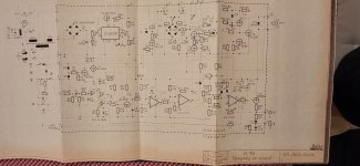
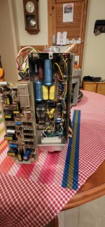
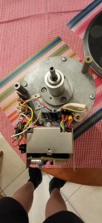
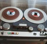
Between 1980 and 1992, the Mechlabor SL 102 record player shown in the picture was driven by the Papst motor shown in the picture and the controller shown in the drawing.
I would like to make a copy of this record player that still works today. I would like to make speed control and display in a more modern design.
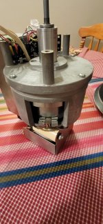
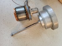
The motor is incredibly quiet because the ball bearing has been replaced with a sinter brass bearing. The shaft run out is less than 0.001 mm.
Bearing gap 0.002mm. So the mechanics are perfect.
Andrew
They could be bipolars. It's an odd way to draw them though. That's what confused me.JFET? I just see BJTs
Its a very old style - the bar is the base and the arrow shows the emitter current passing through it.
Theo pabst sync motors I have worked with all need 90 degrees between the coils. A state variable oscillator will get younthe correct phasing for free. Then two amp's and two transformers and you are on the air. I did this for Rockport a long time ago.
If you want the smoothest, vibration free rotation of a Papst Aussenlaufer motor you should always use a genuine 3 phase supply such as the SG4..
Are the phases at 120 degrees? All the motors I checked (30+ years ago) were 90 degrees. I discussed this with a motor engineer in the us and he validated the solution. You can check th ephase relationship with a scope. just spin the motor and look at the phase relationship.
There are other tricks like varying the drive levle with speed and using a current mode drive to reduce the effect of the harmonics in the less than perfect magnetic structure. It was a very interesting project some 35 years ago.
There are other tricks like varying the drive levle with speed and using a current mode drive to reduce the effect of the harmonics in the less than perfect magnetic structure. It was a very interesting project some 35 years ago.
Most turntable motors have two equal windings, intended for 90 degrees phase shift. At a higher frequency, expect to have to reduce the phasing capacitor by a third.
Yes, the Papst Aussenlaufer motors are almost all 3 phase delta wound motors. I have more than 10 of them, with different numbers of poles and voltages, they all have 3 wires with the same resistance between any 2 wires.
Very good
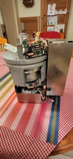
On the picture STM 610 komplet motor end controller power supply. Motor Papst on the picture
STM 610 studio recorder built over 8000 pcs
STM 310 built 3500 pcs
On the picture STM 610 komplet motor end controller power supply. Motor Papst on the picture
STM 610 studio recorder built over 8000 pcs
STM 310 built 3500 pcs
Attachments

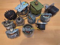
Any idea about the Papst motor in the Elac 50H ? Is it a three phase motor running in single phase ?Here's a photo of the majority of my Papst motors, I have a few others, but they're in use on a couple of my turntables.
Regards,
Anwesh
Yes, most Papst motors in older turntables are 3 phase synchronous motors, with the odd exception being a 3 phase async. motor where there is a need for speed regulation by a mechanical or eddy current control; eg the replacement Papst motor designed for the Thorens TD124/II.Any idea about the Papst motor in the Elac 50H ? Is it a three phase motor running in single phase ?

See if two caps are used to get three phase from single phase, or measure winding resistance.
Or there is a drive of some sort.
That will tell you if it is a 3 phase motor being run from 1 phase supply.
Or there is a drive of some sort.
That will tell you if it is a 3 phase motor being run from 1 phase supply.
You can't get three phases from single phase by using 2 capacitors; a single capacitor provides a phase shift for the second phase and Kirchoff's law provides the 3rd.
I had hoped to answer this question by means of the evidence from all of the motors in the picture I provided above, which, without exception, are 3 phase delta wound motors, but can be used, somewhat less efficiently, by means of a phase shift capacitor.
I had hoped to answer this question by means of the evidence from all of the motors in the picture I provided above, which, without exception, are 3 phase delta wound motors, but can be used, somewhat less efficiently, by means of a phase shift capacitor.
Last edited:
Phase R to phase Y one capacitor, then phase Y to phase B second, equal capacitor.
This was used a lot, it is a valid method, the first cap causes a 120 degree phase shift. Second cap makes it 240.
Another method used is by specially wound transformers, and yet a third method is to wind the motor in that way, combined force and transformer coils.
Without proper details, it is hard to tell at times, particularly in small motors with potted windings.
Last edited:
A lot of 3/4/5/6 phase winding splitters and variable frequency drives are found in industrial drives, those are rated from 100W and out to several MW.
For a turntable, it is an odd item really. Too small...
For a turntable, it is an odd item really. Too small...
Ok, can you show how this would work with a delta wound 3 phase motor? Specifically a 3 phase delta wound hysteresis motor? A schematic perhaps?
Last edited:
- Home
- Source & Line
- Analogue Source
- Papst Motor Question - Changing Rotational Speed by Changing Frequency