In looking at the schematic I realize there are no supply decoupling capacitors on the op-amp pins, you need to add 0.1uF (ceramic cap) from each supply pin to ground in order to assure stability. Not sure about your grounding arrangements, but needs to be low impedance enough to work, fortunately the 4558 isn't too fussy.
Thats a wide variation from Spec ...
<snip>
Indeed, but the newest ones are now 45 years old and that is a very long time in the world for electronics for parts not to drift off of their nominal values. The fact that they even still work after all of this time is amazing given the primitive technology of the time.
(Plus these were extremely cheap cartridges in their time frame and likely had quite large variability even when new. They found their way into everything from inexpensive CD-4 quad systems to bottom of the barrel compact stereos with 8 track players.)
To your question about the voltage polarity to the cartridge, these cartridges have opposing polarity outputs so inverting one relative to the other is necessary, generally it is done with another stage or as is done here the supply voltage polarity is inverted.
Thought so ...
To test the pre-amp you can either plug the cartridge in or connect a 1K resistor across the inputs - you should see somewhere around 3V.
To confirm ... Thats 3 volts ... Not 3mV (spec from panasonic)
Check to make sure your RCA shells are actually connected to the circuit ground, it sounds like something is open.
I'm onto it ....
The op-amp should be fine, not my first choice but adequate for experimentation. (May or may not be a bit noisy)
Just Something available till the correct 1 arrives ...
In looking at the schematic I realize there are no supply decoupling capacitors on the op-amp pins, you need to add 0.1uF (ceramic cap) from each supply pin to ground in order to assure stability
To confirm ... thats 8x capacitors? ... (you mention "Supply pins")
. Not sure about your grounding arrangements,.
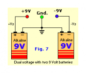
I set the battery connections up as per the attached picture ... which should be as per Schematic ....
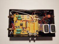
On the other Pic of my board ... Top RHS (near switch) You can see the setup of connection >> 3 lines of wires << i set it as per .....
>> RED = Pos <<>> White = Earth <<>> Black = Neg
Indeed, but the newest ones are now 45 years old and that is a very long time in the world for electronics for parts not to drift off of their nominal values. The fact that they even still work after all of this time is amazing given the primitive technology of the time.
I've been upgrading to the point where it just got too complicated .. (Doing my head in) ...
So i ended going Back to Basics ... Old 70's gear ... with excellent results.
I'll be onto this over the weekend