Pics
Attachments
-
 8C88BB1A-7C35-46B1-9531-023742A8EAA9.jpg1,019.4 KB · Views: 217
 -
 07051A2A-2591-4339-8F22-32E378CDDB9C.jpg929.2 KB · Views: 250
 -
 3396A197-B272-4847-8435-9C6FED7C0030.jpg876.7 KB · Views: 192
 -
 2FBCE308-AF47-418B-8097-E608737C735D.jpg779.6 KB · Views: 207
 -
 60542AD3-30C1-4648-9363-C27CB3D37E49.jpeg572 KB · Views: 177
 -
 FE4D46C3-D1FE-405D-AF42-A592C782D39A.jpg997 KB · Views: 100
How much could i upgrade the caps to with any delay on inrush current (to make it simple)
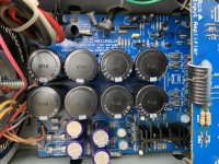
Total capacitance is now almost 40000uf (8x4700uf) But any bigger caps will not fit without heavy mod. How about two screw cans like Nippons U36 that are 22000uf/100v (x2)
Any that can shed a light on this? On my NAD 216 i replaced the caps with 4x12000uf (original was 6x4700uf) and that have been ok for 2 years now.
Not only inrush current but also peak current during recharging the caps when in operation. This peak current can amount to a serious value and happens when the rectified voltage from the transformer is larger then the somewhat discharged caps. The larger the caps, the less they're discharged and hence the less momentary peak currents occur.
So much for the theory.
Until we push the amp out of equilibrium by deliberately modulating it with preferred noise, mostly in the form of harmonic compositions of various kind. Then our cap-chaps will be discharged more, depending on the required notification level and the character of the aformentioned compositions.
The question now is, will the rectifier bridge be capable of passing such higher peak currents and is the transformer capable of supplying this too?
Limits there are. Let it be physical dimensions to stay on the safe side. These amps were not build intentionally to be modified by diy-folk.
Ok, well then i understand little more how it works. Thx for the lesson.
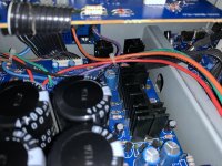
What i know is that the transformer is or should be 1800VA, made by ”TOROID international” for NAD (now Noratel)
By the way Nad call it Hölmgren transformer and it’s so wrong haha, Holmgren maybe.
It has separate windings for the both psu:s (+/-75 and 82) what we talked about before.
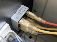
Rectifier bridge is mounted on the heatsink (see pic) and it’s rated 25A and 400V.
I have a fairchild one (looks the same but 35A and 400v new so i was thinking throwing that in.
Also the smaller 1 (or perhaps 1.5) amp for the reg.+/-75 Psu i habe a new one too thats little better of 2A. Fuses here are 2x500mA.
What i know is that the transformer is or should be 1800VA, made by ”TOROID international” for NAD (now Noratel)
By the way Nad call it Hölmgren transformer and it’s so wrong haha, Holmgren maybe.
It has separate windings for the both psu:s (+/-75 and 82) what we talked about before.
Rectifier bridge is mounted on the heatsink (see pic) and it’s rated 25A and 400V.
I have a fairchild one (looks the same but 35A and 400v new so i was thinking throwing that in.
Also the smaller 1 (or perhaps 1.5) amp for the reg.+/-75 Psu i habe a new one too thats little better of 2A. Fuses here are 2x500mA.
Attachments

Such a bridge specified as 25A continuous with a drop of some 1.5V will dissipate 37.5W, so a serious heatsink is needed. But mounted along the main amp sink...
Surge currents can run into ten times the operational dc current, so have the circuit drawings and calculator to see what is the yield. These surges are only a short time in the total period of (rectified) 1/50Hz or 1/60Hz (10msec or 8.3msec), say 2msec max.
These Greatz bridges are great indeed and can handle these surges well (in most cases). Increasing the caps is an argument to increase the bridge too.
That transformer looks solid enough to me, the wires just enough for the job (I don't like wires tied 'floating mid air'). A 2A bridge for the other legs will suffice.
There is a lot to know about transformers, but it is clearifying to realise that a transformer is a kind of electric motor without rotating parts. The 'rotation energy' is 'transformed' into static and saved energy in the caps and challanced by your recreational yet socially acceptable leisure activities (post #43). All you hear and all you don't hear has to pass this lump of metal.
Such a bridge specified as 25A continuous with a drop of some 1.5V will dissipate 37.5W, so a serious heatsink is needed. But mounted along the main amp sink...
Surge currents can run into ten times the operational dc current, so have the circuit drawings and calculator to see what is the yield. These surges are only a short time in the total period of (rectified) 1/50Hz or 1/60Hz (10msec or 8.3msec), say 2msec max.
These Greatz bridges are great indeed and can handle these surges well (in most cases). Increasing the caps is an argument to increase the bridge too.
That transformer looks solid enough to me, the wires just enough for the job (I don't like wires tied 'floating mid air'). A 2A bridge for the other legs will suffice.
There is a lot to know about transformers, but it is clearifying to realise that a transformer is a kind of electric motor without rotating parts. The 'rotation energy' is 'transformed' into static and saved energy in the caps and challanced by your recreational yet socially acceptable leisure activities (post #43). All you hear and all you don't hear has to pass this lump of metal.
Ok i see. How much extra capacitance would you recommend adding in this case? 10000uf extra totally? Would that be safe you think?
The choices i have now is:
2x22000 (2x33000uf max)
or
6x8200 (6x10000uf max)
or
4x12000uf (4x15000uf max)
M
I just don’t know how i can calculate max peak current. I know with my old 216 model (quite similar, same brand of toroid (but 800VA i think) 4x12000uf have been working well without any softstart) or any damage to rectifier (8A)
Sometimes i have seen loads of capacitance like 0.1F or more but my guess is thats with a softstart included.
Would you add a NTC here (seen that in many PA amps)
Last edited:
800VA, say 2x40Vac/10A -> 2x50Vdc/7.5A (approx). 4x12kµF -> 24mF per rail.
C*V=I*t
Absolute peak current from zero: 24E-3*50=I*5msec (only first half of first half rect sine)
I = C*V/t = 1.2/0.005 = 240A
A softstart is recommended, even as this amount of current is a theoretical value. The drawn current will be less due to resistance of wires and the time it takes to change the magnetic field in the transformer. Don't be surprised to measure over 20A (10%) though.
After that, remaining charged depends on continuous drawn dc current from the amp. Say 2A, then during discharge time (approx 80% of 10msec) 16mC is taken from 1.2C (C is Coulomb), 1.3% loss. The same amount recharged from the supply in 2msec yields a peak in that time of 8A.
Resizing to a 1800VA transformer with same other parameters (Vdc, CapµF) does not change the calcs.
Risizing the caps to 33mF per rail gives 33mF/24mF * 8A = 11A^. Doable I'd say.
Ok dioable without softstart you mean?
Another thing. Regarding earlier problem with heatsinks in osu that are way to small, spaceproblems mostly and somebody suggested why not mount them on the big heatsinks? Well, then it will be around 15cm wire to hook them up.. heard it can be problem with performance? I mean not recommend to do that.
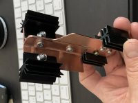
Another thing that can be possible is that i extend the heatsinks with coppersheet (1.5-2mm thick That i bolt onto the heatsinks plus main big heatsinks but then heat has to ”travel” a bit.. so it would be 20-25mm wide and about 150mm long (1x6”) long?
What you guys think?
Another thing. Regarding earlier problem with heatsinks in osu that are way to small, spaceproblems mostly and somebody suggested why not mount them on the big heatsinks? Well, then it will be around 15cm wire to hook them up.. heard it can be problem with performance? I mean not recommend to do that.
Another thing that can be possible is that i extend the heatsinks with coppersheet (1.5-2mm thick That i bolt onto the heatsinks plus main big heatsinks but then heat has to ”travel” a bit.. so it would be 20-25mm wide and about 150mm long (1x6”) long?
What you guys think?
Your mains fuse may trip, depending on characteristics of the device.
Avoid long leads, better enlarge local heatsinks where and how possible.
Avoid long leads, better enlarge local heatsinks where and how possible.
I’m strongly thinking now to add a fan on the back powered from a wall wart. I’m not sure where i could get 5 or litte more volts from the psu to power it without interfering with soundquality.
The fan should be located on the back just behind the hot heater/ resistors
The fan should be located on the back just behind the hot heater/ resistors
I simply cannot appreciate the felt need of using such exorbitantly large smoothing capacitors! Rectifying AC will necessarily force a transformer secondary to supply high current spikes to such capacitors. This puts more stress on:
i) the transformer secondaries
ii) the bridge rectifier
iii) the smoothing capacitors.
As if this is not enough, there will be higher voltage drops in connecting wires and PCB tracks when such charging currents flow. High currents will also generate oscillating stray magnetic fields.
Can anybody explain, or better justify, why a ripple of a few volts in a DC rail of 50V is problematic? Large commercially built amplifiers use far less than 22000uF per rail. For instance, a commercially produced large amplifier with an RMS power rating of 1500W uses 6600uF per rail. This amplifier is a PA amplifier intended for public peformances.
You have a point.
I’ve seen some QSC amps, (RMX 1450) at 2x350w/ 4ohm with 13300uf per rail.
Anyway Is 18800uf per rail enough for this amp then? Can you somehow calculate what value it should be?
Heard also many times manufactures add a lot of capacitance just to cope with a poor xformer. Any truth to that?
I’ve seen some QSC amps, (RMX 1450) at 2x350w/ 4ohm with 13300uf per rail.
Anyway Is 18800uf per rail enough for this amp then? Can you somehow calculate what value it should be?
Heard also many times manufactures add a lot of capacitance just to cope with a poor xformer. Any truth to that?
All mentioned arguments are valid, but it is the question where you want to focus on. DIY's are aiming for 'improving' their equipment in various ways, commercial enterprises balance cost and yields. A mains supply in a classic push-pull topology does not need ultra high values to perform well: here the ripple is mostly 'ignored' (psrr). But it can feel 'safe' and is expected to sound 'better'. All is subjective of course. But don't take away that DIY-fun!
The fun stops then when the rest proves not fit for the intended 'improvements'. Arise will the above mentioned degredations, and along some dissapointments... let's move to another design/topology/holy grail.
The formula to calculate with is trade knowledge used somewhere above: C*V=I*t.
C is capacity, V is voltage-difference (allowed, ripple, charge/discharge), I is dynamic current (important!), t is time (often misunderstood, it's relative)
Consider this: charge time from the wall socket is in a repeating sequence of 50 or 60 Hz AC, thus every (rectifier!) 10 or 8.33 milliseconds to the caps, but only when the voltage remained on this DC supply drops under the top part of the incoming (mains & more-or-less) sinewave, there is this nasty charge current peak (refer to post #51). Discharging of these caps is mainly depending on the audio signal, knowing that most energy demand is around 250Hz (4 milliseconds). There is no classic power supply that is 'faster then the load' except SMPS's (switched mode power supplies), but that's a discussion I leave to another topic/thread for now. The capacitance should be sufficient for the demand, and in correspondance with the surrounding power electronics.
Next is: can you really hear the difference? Double blind A/B test? Sure? And with what program? Your electronic dressed up preference, or a sober recording of real instruments you're custom with due to regular visits to live performances? I doubt if only more then 10% is able to notice this beyond the limitations of subjective prejudice and self overestimation.
Currently I'm enjoying a nice radio broadcast, humble equipment my familymembers can operate too, at a background level. No high end, mediocre hifi, sufficient... enjoyable.
Last edited:
I went with same value: 8x4700uf /100v but changed brand to Epcos. (B41231A9478M000 ) They had higher/ better ripple current than Nichicon LS and CDE 381LX.
I will though add 8x10uf /100v mkt caps (also epcos) in parallel with these.
Another question is In the psu and other places Nad have used 2SA970 and 2SC2240 (Toshiba) trannies and looking for a good replacement that i can easily find with Digikey or Mouser.
I will though add 8x10uf /100v mkt caps (also epcos) in parallel with these.
Another question is In the psu and other places Nad have used 2SA970 and 2SC2240 (Toshiba) trannies and looking for a good replacement that i can easily find with Digikey or Mouser.
Update:
Still working on this project...
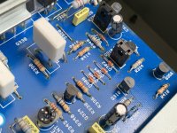
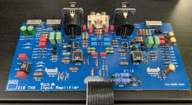
in the reg psu i replaced 1837/4793 to 1930/5171 and the other sd600/sb631k to ksa1220-y and ksc2690.. improved the cooling a lot to and all components on main psu board have been replaced. also input board got re-done with new res and caps (and op amps) IF it works fine i will continue with the rest.
Haven't tried to start it up yet but soon.
Still working on this project...
in the reg psu i replaced 1837/4793 to 1930/5171 and the other sd600/sb631k to ksa1220-y and ksc2690.. improved the cooling a lot to and all components on main psu board have been replaced. also input board got re-done with new res and caps (and op amps) IF it works fine i will continue with the rest.
Haven't tried to start it up yet but soon.
I have tried a lot of different opamps in my amp, but sorry to say that nothing beats the Philips NE5532N which are installed from the factory
Ok, i compared them in my 116 pre to op1612 and while the philips ne5532 isn’t bad i think the 1612 is more balanced and neutral sounding. The orginals ne5532 added some ”colour” to the music which i sometimes like and dislike depending on what you are listening too. Let’s see how the 1612 behaves in the 218...
The upgraded cooling and inputboard.
Will add some decoupling on those legs for the op amps as close as possible.
Will add some decoupling on those legs for the op amps as close as possible.
Attachments

Be aware of the supply voltage for the opamps, in the 218 when rolling😎
What do you mean now exactly? That other opamps pull more current and i get lower voltage or?
- Home
- Amplifiers
- Solid State
- Panasonic obsolete Bjts replacements