I dont' believe that soundcheck is correct on this. A single HDMI link can carry 8 channels of uncompressed PCM - if you go to avsforum and check out the bleeding-edge HTPC folks trying to get HDMI working, some have been successful getting PC software to decode the advanced blu-ray audio content and stream 8 pcm channels to their receivers. I think most success is with ATI cards, but haven't looked that deeply.
I *believe* (but don't know for sure) that you should be able to get 6.1 over HDMI into a panny receiver. However, whether the HDMI sound drivers correctly expose the card for arbitrary audio apps is something of a question.
I *believe* (but don't know for sure) that you should be able to get 6.1 over HDMI into a panny receiver. However, whether the HDMI sound drivers correctly expose the card for arbitrary audio apps is something of a question.
Thanks dwk123,
I'm new to hdmi, so don't know the ground - I looked at the ATI Radeon Sapphire video card which they've had some success with over on AVS! I might spring for one of these - they're relatively cheap €69
I'm new to hdmi, so don't know the ground - I looked at the ATI Radeon Sapphire video card which they've had some success with over on AVS! I might spring for one of these - they're relatively cheap €69
BTW,
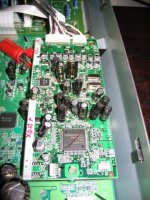
One thing I noticed when I had the XR57 PS board out of the amp was that it had unfilled sections on it marked out "For XR700 Only" - so this board is used also by the XR700!
The unfilled area was in the outputs for +/- 15V & +5V (analog & digital). Does anybody have a schematic for XR700? - I was too tired to trace the connections!
dwk123 said:I dont' believe that soundcheck is correct on this. A single HDMI link can carry 8 channels of uncompressed PCM - if you go to avsforum and check out the bleeding-edge HTPC folks trying to get HDMI working, some have been successful getting PC software to decode the advanced blu-ray audio content and stream 8 pcm channels to their receivers. I think most success is with ATI cards, but haven't looked that deeply.
I *believe* (but don't know for sure) that you should be able to get 6.1 over HDMI into a panny receiver. However, whether the HDMI sound drivers correctly expose the card for arbitrary audio apps is something of a question.
dwk123
Do you mean this one?
http://www.avforums.com/forums/showthread.php?t=672502
Probably not.
I was aware of 5.1 AC3 (7.1) and 2*PCM support.
I am also aware that the hdmi 1.3a should support 8*PCM.
Just let us know your sources. If you're right one more reason to
buy this amp! 😉 Of course we'd need to make sure that the amp supports it.
If you're right, I'd be very interested why Asus built 3 HDMI interfaces on one soundcard?
Cheers
Have you guys seen this thread about a full DIY amplifier based on the equibit chips used in the SA-XR amplifiers? http://www.diyaudio.com/forums/showthread.php?s=&threadid=91148
Yes, iampivot,
Seen the thread referenced. It is the reference I look up when I'm planning mods. For instance, battery drive of output stage is mentioned in the thread along with other ideas.
Any news CrazyD? I'm waiting on my clock & kit to arrive. I ordered clock on 17th from Guido Tent but don't know if it has shipped yet?
I ordered clock kit & regulated supply kit from here, excellent prices & I believe the kits will be the same http://www.awdiy.com/
I believe these kits are done by a DIYA member stef1777 - see thread http://www.diyaudio.com/forums/showthread.php?s=&threadid=102277&highlight=lt3080
iampivot said:Have you guys seen this thread about a full DIY amplifier based on the equibit chips used in the SA-XR amplifiers? http://www.diyaudio.com/forums/showthread.php?s=&threadid=91148
Yes. Koon is doing a great job over there. You should also have a look at koonlab.com.
He is running some more real sophisticated DIY-Audio projects in the digital arena. Have a look at his FIR filter approach. Just amazing to use the GPU as processing engine for your filter calculations.
I am planning to use his amp boards, once he got the new amp layouts finished. He seems to have played 😉 with Pana XRxx and Tact before and was not quite happy with it. 😉
Cheers
Just looked at Koonlab.com - innovative work - I thought Peufeu was the only one doing this level of hardware/software project but Koon seems to have completed similar - very creative!
I'm looking at his schematics to get some ideas on mods to the Panny amp - his discrete variable voltage PS vol control doesn't look too difficult & he reports it
Some other great ideas/projects on the site - Thanks for the link, Soundcheck
I'm looking at his schematics to get some ideas on mods to the Panny amp - his discrete variable voltage PS vol control doesn't look too difficult & he reports it
Silky, and warm, but powerful. Rock solid voltage supply. Fully satisfied.
Some other great ideas/projects on the site - Thanks for the link, Soundcheck
eld said:Hi guys,
Just wanted to report my latest round of mods and the results.
Mods:
1) Replace the stock C707 with a Jensen 4-poles 1,500uF/200V cap. Cut tracings to isolate input and output lines. ($62)
2) Replace the stock diodes bridge with a DIY Fairchild Stealth II diodes bridge. ($5)
3) Added two Panasonic TS-HA 15,000 uF caps after the ZE caps and before the Nichicon KZ/ Vishay caps. ($20)
4) Rewire the power lines to directly connect to the + and - tracings of the main board from the power board.
On a side note: I upgraded the power outlet to a FIM 880 (G)
After a week of listening from low to high volume, I can say that the results of the latest mods have elevated the Panny to an exceptional level. The 2nd harmonics are all there now in great details and depth. Violins and pianos sound natural and smooth. Imaging is rock solid. The stock sonic signature is still there, but the depth, smoothness, and soundstage are so much better. I'm very happy with the results. I think anything else that is done from this point on is just icing on the cake.
Nicely done eld.
Next step, you may want to try replace some of the electrolytic caps on the DSP board with OSCON or blackgate. This will further reduce the noise level and enhance the details.
Mike
Hey Mike,
Thanks for joining in here & I was thinking along these lines but most of the PS bypass electros (These are the ones you're talking about?) are SMD Can type that I don't know how to desolder from board without damage. Can you say how you did this?
I also was thinking also of supplying a clean 3.3V supply to this board & a new 24.576MHz clock to the DIR chip. These are my next mods after I have finished the current tests.
I'm testing different caps in the output section where the existing 1000uF Panasonic XE water caps are. These operate as bypass caps for the PS that feeds the H Bridge driver. So far preliminary signs are that Black gates are pretty good here but I need to get some burn-in time on them ( I have STD, C, K & non-polar in various values to try)
Other things I'm testing are changes to 0.47 cap after the output inductor currently a Panasonic brown metallisied polyester film cap & again early indications are that there's a subtle change using metallised polyprop.
Final test are with changing the output inductors to Amidon T106-2 10uH - bigger than the existing inductors (does anybody know what these are) & width may well be a problem to fit 14 in. I wonder if some could be mounted under the board laid flat to make room. WOuld this have a bad effect on the ground plane which covers the bottom of the board or any other neg effect?
I did also think of disconnecting the circuit that comes after the output inductors & caps etc. - this circuit consists of two transistors, various caps & resistors, diodes - it spans the hot & cold output signals of each channel leads back to a circuit on page 81 of XR57 schematic which says "speaker level" & "Muting switch". I've wondered what detrimental effect these circuits might have on the sound. Disabling on one channel s not that difficult (removing two 220K Rs) but I would like t know more about it before I touch it
Anyway lots of tests to try & will be reporting back here when I have some results.
One other thing - in thinking about my battery test which didn't live up to expectation, I realised that the battery wasn't new & probably was not very strong so this might account for the lack of dynamics I heard in the sound - I'm going to parallel a number of batteries & test again!
Phew!!!
jkeny said:Hey Mike,
Thanks for joining in here & I was thinking along these lines but most of the PS bypass electros (These are the ones you're talking about?) are SMD Can type that I don't know how to desolder from board without damage. Can you say how you did this?
I changed out the surface mount electrolytics with leaded blackgates. All you have to do is having two soldering irons and apply heat on both sides of the cap and the cap should come out easily as not much heat is needed. It's not much effort but very worthwhile.
Here is a pic of the DSP mod.
Mike
Attachments
Koon keeps the pace on PCM2PWM:
http://www.diyaudio.com/forums/showthread.php?s=&threadid=119917
Cheers
http://www.diyaudio.com/forums/showthread.php?s=&threadid=119917
Cheers
Thanks Mike,
I read that somewhere, will give it a try. I was going to use OsCons as replacements! You have soldered these new caps onto solder pads which aren't thru-hole - why aren't they lying down? I see you didn't do all the caps any reason?
I see two non polar Black Gates peeking out from under the board - where did you use these?
You haven't done the clock mod I see - any plans?
Edit: Yes, Koon is the man - I may well try building his 2 channel TAS5706 when I finish this - he is giving a lot of useful work to the DIYA inmates!
just worked on a PANA home theater (one of the all-in one receivers with dvd changer, etc...) yesterday. it was a parts replacement for another tech that has been shotgunning it for 4 months. he's on vacation and i drew the short straw. before installing any of the parts he ordered, i reassembled the unit and powered it up. i found the problem in just a few minutes, the amp chips weren't getting a clock signal. the culprit was a shorted flip flop chip in the clock circuit. the other tech had ordered ALL of the silicon for the amp board. i think a training session on class-d amps is in order for our shop.
Well done UncleJed, we need men like you around - not just mindless "replace the board" type engineers!
Hey Mike,
I thought my DSP board looked different to yours - of course, just remembered, your amp is XR45 & you did the clock change! Your audiocircles thread is where I got a lot of the inspiration for these mods - thanks again.
I'm just about to do the clock mod now - wish me luck!
I thought my DSP board looked different to yours - of course, just remembered, your amp is XR45 & you did the clock change! Your audiocircles thread is where I got a lot of the inspiration for these mods - thanks again.
I'm just about to do the clock mod now - wish me luck!
jkeny said:
I read that somewhere, will give it a try. I was going to use OsCons as replacements! You have soldered these new caps onto solder pads which aren't thru-hole - why aren't they lying down? I see you didn't do all the caps any reason?
There is no room to lay down the caps as they are pretty tall. There is only standing room 🙂
All I changed was the caps associated with the signal path, digital receiver and the DSP chip. I did not change out the caps for the microprocessor as that has no effect on sound quality.
I see two non polar Black Gates peeking out from under the board - where did you use these?
I changed out the two coupling (series) caps on the subwoofer channel with Blackgate non-polar (N) series but did not notice much of a difference.
You haven't done the clock mod I see - any plans?
When I took this picture, I have not installed the hagclock yet. The clock would be hanging off this DSP board with wires going underneath to the AK4114 clock pin.
I don't remember if the XR57 also uses the AK4114 receiver. One more thing I did was to convert one of the optical input to a coax input with a Scientific Conversion SC947-02 tranformer. It was a very nice upgrade compared to the original coax and the optical input.
Mike
So you basically replaced all these SMD electros except for the uProcessor ones - is that correct?
I just tried my new Oppo 980H universal DVD player via the HDMI output into the XR57 & it's better than the SPDIF input with more nuances, emotion in the sound - probably hearing more micro-detail.
I haven't finished the clock mod yet - will be done tonight & report back here!
I just tried my new Oppo 980H universal DVD player via the HDMI output into the XR57 & it's better than the SPDIF input with more nuances, emotion in the sound - probably hearing more micro-detail.
I haven't finished the clock mod yet - will be done tonight & report back here!
jkeny said:So you basically replaced all these SMD electros except for the uProcessor ones - is that correct?
That's correct.
I haven't finished the clock mod yet - will be done tonight & report back here!
Looking forward to hearing what you think about the tent clock.
Mike
I didn't buy the Tent clock in the end - very bad customer service - basically he didn't ship my clock or answer my emails - After 8 days I got a refund when I raised a Paypal dispute.
I bought a small neat cheap (€14) clock kit from here: http://www.awdiy.com/index.php?page=miniclock
and a VCXO from Digikey cost $3
So all-in-all I saved myself €40 - the cost of tent clock
Haven't had much time to listen - will have a good listen tomorrow & report!
I bought a small neat cheap (€14) clock kit from here: http://www.awdiy.com/index.php?page=miniclock
and a VCXO from Digikey cost $3
So all-in-all I saved myself €40 - the cost of tent clock
Haven't had much time to listen - will have a good listen tomorrow & report!
- Status
- Not open for further replies.
- Home
- Amplifiers
- Class D
- Panasonic class D amps