😀
So... We can drink a scotch and tequila for pre board B, which could have been damaged but is not. It's not really easy to hear subtles 'cause the speakers i use right now are cheap and old. But it really seems to work fine.
Pre board A hasn't repaired from itself, of course, so it has some problems.
Again, it's difficult to say, but what we got is:
- lot less power
- kinda distorted sound
- kinda background hiss noise from the very moment the power amps relay closes the contacts.
These are the acoustic symptoms i can tell right now.
Two things to say: i used the B power board only, the A one is ok and the bulb never turned on during playback. I got 100 w bulb, and i guess it would lighten if i would put a 60 w one.
Is it a start?
Yes, if you have a good op amp board with a good reading power supply board, and an output board putting out <200 mv DC, by all means try them - on load resistors or $4 speakers from the charity resale shop or auto junkyard. I picked up a nice 10 ohm 10 cm x 25 speaker two weeks ago at Salvation Army resale for $3. Labled GM Delco.
It's not the time on the airplane that is dangerous, it is the landings IMHO. Unless one is big and has leg circulation problems sitting still. Plus the hassle at the airport getting on; I'm not taking my shoes off in public, period. Capezio dancing shoes (organ shoes), yes, bare feet no. Airlines are making wads of money this year, I don't suppose they will be changing any boarding procedures. I haven't flown since the Paris trip 2005.
Edit, you did a test while I was typing. Okay, if the two good boards work well together, try them with no limiter, on trash speakers, and if still no DC after a thermal cycle, assemble that amp.
distorted pre board can be power supplies, (if both channels), a potentiometer wiper lost contact or losing contact, a cold solder joint losing contact, or a bad coupling capacitor (in and out of the op amps). How old are these units? I don't test electrolytic caps over 10 years old, if the amp has problems, out they all go. The freight on the box from farnell warehouse is as much as all the caps, usually. But I change parts 2 at a time between auditions, I make a few cold solder joints, and rarely a layout error. Distortion and hiss can also be oxidized contacts somewhere, like a push in connector between boards.
Last edited:
They are quite new, like 2-3 years old and really barely used.
What's exactly a thermal cycle?
Yeah, you remind me: it's on both channels, my impression is that on ch 2 i've got more of it, but as i said before, it's hard to tell.
I got some new op amps as spare parts, btw. I would hate to desolder them, though. It would end in a mess, i think.
What kind of tactical approach would you use, i don't have any signal tracer (yet), so i could use the xlr input attached to a signal generator, if that could help.
Another thing: what do you mean exactly with "like a push in connector between boards".
Thanks indianajo.
Flying fear is more psicological, or psycosomatic. I could write a book about it, don't think humanity needs my opinion, though.
now it's going to get tougher without other resources like a signal tracer and/or an oscilloscope.
so you may have to replace alot of components to eliminate your distortion problem but if your up to it make a chart with measurements from all the op-amps on the board (all with respect to ground and be careful not to short between pins!) i've got a hunch that some of the interstage coupling caps are going to be leaky.
i just saw a new post: if you've got a signal generator that will help. make two sets of readings (one no signal) ( one with)
Last edited:
indiana you need a BLT (bus line tracer) it makes finding leaky caps and shorts on a board a snap and pays for itself by saving alot in replacement components (more money for travel and your favorite libation )
A thermal cycle is running the amp until it is warm, then letting it get cold again, then turn it on again and see if it still has no DC and decent sound.
I would suggest op amps are not the most likely parts to cause distortion. Solder bridged pins maybe on the board, but you've gotten rid of the short.
Press fit connectors are ones that have a little fork and you push the insulated wire into the fork which cuts the insulation and touches the wire. Ribbon cable connectors are like that. The factory pushes the ribbon cable in the block and uses a special machine to push down and make the pinch connections. These don't have much contact force, which doesn't exclude the air, which means after a few years the brass or tin oxidizes and the signal don't make it through at low voltages, like in soft music. 1-2007492-5 - TE CONNECTIVITY - CONNECTOR, SFP+, RCPT, 40POS, PRESS FIT | Newark element14 US
I use a battery transistor radio as a signal generator. The beats of rock music on the pointer of my Simpson VOM meter on 20 vAC scale help me determine if I've got music at that point, or oscillation.
BTW, ultrasonic oscillations can make music distort, also. I'd try to track the bad sound to a particular potentiometer at first by wiggling the knobs back and forth to scrape the oxide off. Those tone controls on the op amp page are a bad design that don't have any redundant path when the pot wiper oxidizes (as they almost all do eventually).
The "bus line tracer" must be the name now of the hall effect dc current probe I saw at a seminar 30 years ago. I tried to find one on newark yesterday, all the current probes have a ring that goes around the wire- not useful at all on PC boards. The only way to buy an Allegro analog hall effect IC, you have to be able to etch surface mount boards. ^&*)(*(&^%! Honeywell used to make Hall effect IC's in TO92 packages you could stick on a little scrap Nema-C board with a battery and connect it into your DVM DC volts scale.
Roger.
I could grasp an alalog voltmeter from my neighbour, Indiajo. It's obviously a cheap one, but maybe it could substitute your Simpson?
I use the ipad as generator.
I start the measurements of the 4558s, it will take a while.
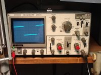
I uploaded a picture of my oscilloscope, as you can see the trace is crooked. But maybe, we can use it anyway. Actually it would be the first time i would use it.
Edit
I posted a picture with a first measurment results, written by hand (hope you understand).
Vertical (y axis) are the pins 1-8, horizontal (x axis) the number of the IC.
Dmm on DC, black probe to ground.
I wrote the actual sounds i heard. White field means no actual voltage (like 0.0002 v or so). If we are talking of mV, then i got to change the range.
I wait🙂
I could grasp an alalog voltmeter from my neighbour, Indiajo. It's obviously a cheap one, but maybe it could substitute your Simpson?
I use the ipad as generator.
I start the measurements of the 4558s, it will take a while.
I uploaded a picture of my oscilloscope, as you can see the trace is crooked. But maybe, we can use it anyway. Actually it would be the first time i would use it.
Edit
I posted a picture with a first measurment results, written by hand (hope you understand).
Vertical (y axis) are the pins 1-8, horizontal (x axis) the number of the IC.
Dmm on DC, black probe to ground.
I wrote the actual sounds i heard. White field means no actual voltage (like 0.0002 v or so). If we are talking of mV, then i got to change the range.
I wait🙂
Attachments

Last edited:
it certainly looks like U7 is bad (other than supply pins there should be no DC on inputs or outputs)
hope your solder/desoldering skills are good!
the picture of your scope didn't come through but that will help!
it's not the x-over section like i first thought
hope your solder/desoldering skills are good!
the picture of your scope didn't come through but that will help!
it's not the x-over section like i first thought
Last edited:
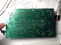
Here you have the scope!
Are we sure that it's the IC the problem?
Btw, as far as i understand, this ic controls the out xlr only..
My soldering skills are not good, i have to admit.. Before i touch this, i try to desloder an IC from a scratch board, i would say.
Are we sure that it's the IC the problem?
Btw, as far as i understand, this ic controls the out xlr only..
My soldering skills are not good, i have to admit.. Before i touch this, i try to desloder an IC from a scratch board, i would say.
Attachments
i don't who else is part of the "we" but preliminary indications spell trouble for U7(we still could be dealing with bad capacitors but removing U7 will help us (or you) determine what's going on)
if after a bit of practice you get U7 off the board try running signal through it again and let me know what you've got (and before you ask yes i mean no ic at U7)
what are you using to desolder? a vacuum style solder pull or wick or both?
if after a bit of practice you get U7 off the board try running signal through it again and let me know what you've got (and before you ask yes i mean no ic at U7)
what are you using to desolder? a vacuum style solder pull or wick or both?
Last edited:
Ok. That means: i have to replace it anyway. Hopefully it's my lucky day.
Another thing.. Look at the left of the picture, the board is cracked. It's the ground trace...
I start desoldering the bad Ic..
Edit
I use the pump. I got some wick but either it's bad or i am not able to use it.. It doesn't work.
Another thing.. Look at the left of the picture, the board is cracked. It's the ground trace...
I start desoldering the bad Ic..
Edit
I use the pump. I got some wick but either it's bad or i am not able to use it.. It doesn't work.
Attachments
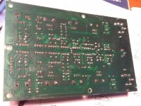
sorry can't see the crack your referring to if you use something like a pencil or pointer to show the area it would help.(i think i should buy you a magnifying glass for christmas) insure that the crack isn't causing loss of ground install a jumper across it and check continuity after.
if your wick doesn't seem to work try rosin softened with acetone so it's like soft butter or a thick oil.
the rosin should be easy to find after all you live in the country that produced the greatest violins in the world 😀
if your wick doesn't seem to work try rosin softened with acetone so it's like soft butter or a thick oil.
the rosin should be easy to find after all you live in the country that produced the greatest violins in the world 😀
Last edited:
If you have a scope that works, you don't need a VOM. I have two broken scopes, no more used ones will be purchased. An ultrasonic oscillation is a high frequency (short period) sine wave, usually above 20 khz. thats less than 50 microsec period. Rock music has amplitude that goes up and down with the beat about 60-100 bpm or however fast they are playing. Music has most of the volume with period longer than 1 ms.
Before I started pulling any soldered in op amps, I would check the wiring integrity very carefully from pin to pin, not on the board side. A three year old device could have some cold solder joints coming and going. You can use ohms scale of the DVM, 4558s are pretty tough. Before going to ohms on the DVM, measure the power pins or capacitors as below 20 mv, and if higher, discharge the small capacitors with an alligator clip lead. (Don't use an alligator clip lead short on the big mains capacitors, use a resistor between 470 and 7500 ohms). of course this is with the power sources unplugged. then the wiring point to point on the op amp legs should read just like the schematic diagram.
I can't see the break, but that doesn't mean you can't. I had to jumper some burnt lands on the driver boards of my 1300 watt amp.
Solder wick won't work if you soldering iron is not high enough wattage, or if the iron tip has a conical pointed tip instead of a wide screwdriver tip.
Remember pin 1 of a DIP IC is on the letter side, (top) left on the indent end or the one with the dot by it. On the bottom side, pin 1 is top right.
edit, have you wiggled the w50k and w100k pots to clean the wiper off and see if that causes the distortion to diminish? U7 is just the signal out driver, you won't hear problems with that in the speaker.
Note that if DC comes out of your input jack, it may blow up your cell phone or whatever expensive device you are using as a signal source. I pulled my transistor radio signal source out of the trash, then bypassed the bad volume pot with a fixed resistor.
Last edited:
yes play some music or remeasure(for DC) at the pads(U7)to see what you've got (open ground trace repaired of course)
Last edited:
Indianajo, i already tested it, i discover only now your answer..
Guys.... IT SEEMS TO WORK FINE!
I'm not becomin enthusiast, but i can't tell any difference of sound quality and power with the other board.
The intrinsec quality of the speakers i'm using now is low, really low, so i don't know how much distortion i could have. But it's definitively another planet.
I just removed U7, period. I got replacement, though.
I'm happy 🙂 🙂
Edit
How can i repair the ground trace? Never done it before..

repairing the gnd trace is easy scrape away the green solder mask to expose the copper and solder a wire jumper (but if everything worked do you really need it?)
Take a piece of solid core small gauge wire. I use AWG 28 wire wrap wire I got from a surplus shop. It is silver plated. Cut it about 2 cm longer than you need, strip 6 mm off each end, make curls in the end with a needle nose pliers, both curls in the same plane. Put the curl of one end around an IC or component leg at the signal source. Reheat the joint and push down on the wire with a pick. It should sink into the solder joint. If you still see the top of the wire, add a little more solder. Do the other end at a joint after the break the same way. Glue down the middle of the wire with Duco (rubber) cement or something else not very permanent. Silicon seal caulk I used to use only sticks things on a year, don't use that. Wallboard adhesive works too, but only comes in 9 oz tubes and makes a real mess if it doesn't stop flowing when you stop squeezing the applicator.How can i repair the ground trace? Never done it before..
- Status
- Not open for further replies.
- Home
- Amplifiers
- Solid State
- Pa Amp repair - any help?