The PCB images are your creations. There is no problem with these.
This discussion could not have proceeded without that information.
But, this thread is yet more advertising for the ESP creations and services.
This discussion could not have proceeded without that information.
But, this thread is yet more advertising for the ESP creations and services.
I don't see it as advertising at all. Someone having no affiliation with Rod expressed interest in making a layout for the P3A (a very popular amp by any standard). People responded with advice on how to layout the board, which certainly does not help Rod's business.
Carlos makes a valid point that sharing private board designs and help with those designs should be done judiciously.
I personally have my own design for the P3A, I spent alot of time on it and more money than if I had just bought the boards. I will not be sharing the design due to my own conscience and while I encourage DIY design of boards, I do not think Rod is overcharging for his boards and support of his designs.
-David
Be happy folks, and let Rodd be happy too
Enjoy and share your ideas and go producing fun to everybody.
Moderators do not use to make such kind of intervenctions, as this belongs to the personal conscience...up to you guys.
Also, if our forum does not protect Rodd, will also not protect Peter Daniel that has announcements here... regular, legally paid.... if someone publish boards to the chips Peter announces will not be a problem too.
The problem with rules, is that... when we create rules, or the absence of rules, we have to obbey them too.... so.... create rules is something that has two directions...goes outside yourself to apply other folks and, of course, you have to obbey them too....... freedom is better..... i do think this way.
Same rule is applied to all folks.... yep... this is fair
Go ahead,.... C'a marche!
Carlos
that's yet another advert for ESP.gtforme00 said:I don't see it as advertising at all. .......................
I personally have my own design for the P3A, I spent a lot of time on it and more money than if I had just bought the boards. .....I do not think Rod is overcharging for his boards....
The whole thread makes readers aware that;
1.) ESP exists.
2.) ESP has capable design solutions.
3.) ESP sells PCBs that work.
4.) ESP gives service & back up.
5.) ESP has a good reputation among DIYaudio members.
What better advertising does ESP need?
I have used several of Rod's designs. Some I have changed to suit my needs. These are specific to the project and I don't have any reservations about showing the board layout of those.
The ones that I've used without changing I do not show (includes a P3A layout), as I think that this is not being fair to the source. Rod shares these designs for us to use freely, for our own purposes. To publish an alternate layout of the exact design is not the way I'd go about things.
The ones that I've used without changing I do not show (includes a P3A layout), as I think that this is not being fair to the source. Rod shares these designs for us to use freely, for our own purposes. To publish an alternate layout of the exact design is not the way I'd go about things.
AndrewT said:that's yet another advert for ESP.
What better advertising does ESP need?
He deserves more than he gets. The wealth of reliable information that is available in one place is incredible and worth referring people to.
And the amp sounds superb. It's so good I don't dare buy other amplifiers- in case I lose that magic to the music...
I've built 2 channels, and have boards/parts for 4 more, but no time.
I wish he sold complete, tested and ready to plug and play versions...
I've built 2 channels, and have boards/parts for 4 more, but no time.
I wish he sold complete, tested and ready to plug and play versions...
AndrewT said:
The whole thread makes readers aware that;
1.) ESP exists.
2.) ESP has capable design solutions.
3.) ESP sells PCBs that work.
4.) ESP gives service & back up.
5.) ESP has a good reputation among DIYaudio members.
Yet more advertising!
Ok so I conceed this thread may be a form of advertising, just not of the paid for variety and certainly not out of undeserved merit. Word of mouth is definitely a powerful form of advertisement. Word of mouth is also a double edged sword, but I have yet to see anyone speak badly of Rod's business practices or designs.
-David
P.S. Back to the topic, the extra capacitance (~100uf) at the rails was necessary on my (own design) boards to prevent oscillation on the negative rail. I left myself the provision to mount a separate heatsink across the drivers and q9, but have not found it necessary to exercise that option even after long periods of high output testing.
This has gotten crazy round' here . No posting boards???
What is DIYaudio for ? 😡
This brings back recent memories of a ESP (oops,more advertising)post for instructional purposes that caused
moderation.
The P3A is not rod's amp anyway (his representation of it is
copyrighted,on his site), but the circuit I remember well as
a teenager (RCA,pop. Electronics). He openly admits this
on the P3A page
Would not a radically different layout or the change of just a
few components on a amplifier be a new design. ?😕
(Elliot did it and called it the P3A)
Did you know that Rod's Project 61
So lighten up..post them boards,change them parts,DIY!!!
OS
What is DIYaudio for ? 😡
This brings back recent memories of a ESP (oops,more advertising)post for instructional purposes that caused
moderation.
The P3A is not rod's amp anyway (his representation of it is
copyrighted,on his site), but the circuit I remember well as
a teenager (RCA,pop. Electronics). He openly admits this
on the P3A page
This amplifier does not claim to be "state of the art", and in fact the base design is now over 20 years old.
Would not a radically different layout or the change of just a
few components on a amplifier be a new design. ?😕
(Elliot did it and called it the P3A)
Did you know that Rod's Project 61
was the ASKA amp ,so Rod's no angel either.This was a contributed project, and it has now been retired at the author's request.
So lighten up..post them boards,change them parts,DIY!!!
OS
ostripper said:
So lighten up..post them boards,change them parts,DIY!!!
OS
Let's put it this way: I don't know how many of the P3A boards Rod sells, but I don't think it's making him millions. Is it, along with the other sales, enough to keep his ultra informative site up? Apparently it is. For me, this is worth protecting.
In the end, it's up to the individual what he or she wants to do, based upon their ethics.
I have my own rules that I live by.
By posting about this I feel we are all inadvertantly giving
rod alot of support. A side effect of this posting will :
1-give ESP more hits on google.(already confirmed,"googlebot"
already has crawled this thread.)
2-More will go to his EXCELLENT site to become more
knowledgable.
3-Even if 1% of the above buy boards, all is well for Rob.
My point was that board posting will benefit both parties
in the end ,as some are not inclined to produce boards anyway
opting instead to buy otherwise unbought boards from rod.
To finally put this to rest, while reading Rob's "hall of shame"
Cool guy, I never really went to this part of his site.
P3A- copyright Rob Elliot..
Putting this aside.. back to the layout,
Also, A 10 ohm resistor between the remaining "dirty ground"
and input /DC blockingcap ground.
My conscience is now fully at rest.
rod alot of support. A side effect of this posting will :
1-give ESP more hits on google.(already confirmed,"googlebot"
already has crawled this thread.)
2-More will go to his EXCELLENT site to become more
knowledgable.
3-Even if 1% of the above buy boards, all is well for Rob.
My point was that board posting will benefit both parties
in the end ,as some are not inclined to produce boards anyway
opting instead to buy otherwise unbought boards from rod.
To finally put this to rest, while reading Rob's "hall of shame"
He encourages us to post his material with proper acknowledgement (to increase traffic to his site😀)Normally, I don't have an issue with use of my material for educational purposes. What I do expect though, is a reference to the original material, and acknowledgement.
Cool guy, I never really went to this part of his site.
P3A- copyright Rob Elliot..
An externally hosted image should be here but it was not working when we last tested it.
Putting this aside.. back to the layout,
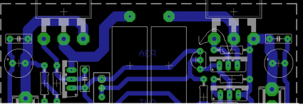
I leave the Zoble off the board ,put it on a little solder terminal board( "daughtercard") or right at the output terminals.CBS240:Just a few points.... I would at least fill the empty space with copper. I would also take the negative feedback from a point in the center of where the two output resistors connect, that being node labeled "OUT", where the Zobel now resides. Having the DC blocking cap grounded to the same trace as the decoupling cap might create issues as well.(Buzzzzzzz) It needs it's own ground trace, a clean ground trace, without the current pulses from the decoupling cap corrupting it, such as the signal GND. Does Q9 need to be mounted to sense the temperature of the drivers, Q's 5 & 6? (reffering to the scematic here ) Typically with a feedback pair OS the drivers have to be thermally compensated, but maybe not here....I haven't built this one.
Also, A 10 ohm resistor between the remaining "dirty ground"
and input /DC blockingcap ground.
My conscience is now fully at rest.
ostripper said:Did you know that Rod's Project 61
was the ASKA amp ,so Rod's no angel either.
You are implying the wrong thing here.
Putting this aside.. back to the layout,
I leave the Zoble off the board ,put it on a little solder terminal board( "daughtercard") or right at the output terminals.
Also, A 10 ohm resistor between the remaining "dirty ground"
and input /DC blockingcap ground.
My conscience is now fully at rest.
Agreed.🙂 That seperation in PS gnd and signal gnd is important, and that both inputs of the differential are referenced to the same gnd so your not amplifying the difference between them.😱
CBS240 said:
Agreed.🙂 That seperation in PS gnd and signal gnd is important, and that both inputs of the differential are referenced to the same gnd so your not amplifying the difference between them.😱
treat the signal ground as an input that is just as sensitive as the "conventional input". Take the signal ground and it's three connections: NFB return, Zin return, RF filter return, back to the input socket and then connect the input socket to the Audio Ground.
By
greg:You are implying the wrong thing here.
Only the truth. He is human (not an angel )and makes mistakes as we all do. 🙂
I'm wondering why does the designer (R. E.) recommends 75mA bias current in the OP stage (2*25mV on the 0.33r resistors).
For an EF OP stage 25mV drop on the Re is the ideal value, but for a CFP OP stage far less is enough. Say 2.5mV.
Then bias current would be 7.5mA (2.7mA for driver, 4.8mA for output).
Anyone please who has built the P3A project would make some measurements & a listening test with ~7.5mA bias?
For an EF OP stage 25mV drop on the Re is the ideal value, but for a CFP OP stage far less is enough. Say 2.5mV.
Then bias current would be 7.5mA (2.7mA for driver, 4.8mA for output).
Anyone please who has built the P3A project would make some measurements & a listening test with ~7.5mA bias?
It was long ago , but I remember seeing crossover distortion
below 10ma ,but this was with older 2n3055/2955 OP pair.
I finally settled with 50ma per device.
below 10ma ,but this was with older 2n3055/2955 OP pair.
I finally settled with 50ma per device.
in my version
i a was happy at 50 ma per device .....but mostly i use mjl 1302-3281 and noticed that with original toshibas 1302-3281 works with even less ....
i have never heard this amp with 3055-2955 and also the best version i ve ever built was with the original toshibas ( still have about 150 pcs ) 2sa 1302 2sc 3281
regards sakis
- Home
- Amplifiers
- Solid State
- P3A layout