Hey Ajju,
What I'm going to say might disappoint you. The active X/O I've put together is a straight forward 4th order L/R crossed at 201hz. It has a baffle diffraction circuit setup at the input which doubles up as the input buffer as well.
At the moment a Linkwitz transform is coming together to push the sealed sub to an F3 below 50. I'm still pondering about a 3-way without the passive in-between the mid's & tweets. Problem is, many people have commented negatively about the phase which supposedly is so bad, they image terribly.
cheers,
sunil
Problem is, many people have commented negatively about the phase which supposedly is so bad, they image terribly
Correct me if i am wrong.!
Have u tried using some thing like a bessel allignment, which might give u a better phase response, ofcourse at the expense of a steep roll off.
Regarding state variable filters, the biggest advantage i feel of using these is the fact that they are relatively immune to component tolerances. And by employing just 3 opamps u get all 3 responses. It further adds flexibilty in that u can continuously change the filter cutoff frequency, with a minimal set of controls, or even alter the Q of the system independently.
Btw what kind of amps do u use after the filters...
just curious...!!
Vivek:
For baffles i am using speakerworkshop, It is freely downloadable from the web. For all the analog simulations i am using a student version of Microsim Pspice 6.3.
ajju
Svante, Sreten (these are the only ppl whose response i've seen):
and all others who might have been browsing this thread in the background...😀
Could you please let me know your opinion on the x/o and the graphs..What does experience tell u...Am I proceeding in the right direction..or am i lost?
and all others who might have been browsing this thread in the background...😀
Could you please let me know your opinion on the x/o and the graphs..What does experience tell u...Am I proceeding in the right direction..or am i lost?
ajju said:Svante, Sreten (these are the only ppl whose response i've seen):
and all others who might have been browsing this thread in the background...😀
Could you please let me know your opinion on the x/o and the graphs..What does experience tell u...Am I proceeding in the right direction..or am i lost?
No, I think they make sense. I have not looked deeply into the schematics or verified the details of the response, but the simulation seems OK. Just at the crossover, it seems as if the two branches play in kind-of-opposite phase, since the blue curve is below the others. Why the impedance compensation?
A warning might be in place though, in that the responses of the drivers are not modeled. These include magnitude effects, but also phase effects. It could be that the phase responses of the drivers will lead to strange effects when adding the acoustic outputs. But I guess you have realised this.
Still, this simulation is far better than just assuming that the drivers have a constant resistance Also, the prediction of the impedance seen by the amplifier is probably dead right. 😉
ajju said:Svante, Sreten (these are the only ppl whose response i've seen):
and all others who might have been browsing this thread in the background...😀
Could you please let me know your opinion on the x/o and the graphs..What does experience tell u...Am I proceeding in the right direction..or am i lost?
simply put......
If you put the crossover I originally suggested into your model
(note the changes for the tweeter) and get good results then
your model is not too far off either.
But I suspect you won't........
for the reasons Svante outlined earlier and also
not accounting for baffle step correction as well.
I'll also note the circular bass unit housing will have
particularly difficult diffraction issues to deal with,
the tweeter due to its mounting much less so.
🙂 sreten.
Svante said:
Just at the crossover, it seems as if the two branches play in kind-of-opposite phase, since the blue curve is below the others. Why the impedance compensation?
A warning might be in place though, in that the responses of the drivers are not modeled. These include magnitude effects, but also phase effects
Yes, I do understand the fact that i'm never going to see these curves in the prototype...
The impedence compensation has been added to nullify the tweeter resonance that peaks the overall impedence curve at around 1khz. I tried adding the compensator just in front of the tweeter model but, it dint take much effect. So i added it paralelly so that atleast the amp sees a sane impedence 🙂
Also I was a bit worried about the phase response at crossover. there is defenitely a huge phase difference there...
sreten said:
If you put the crossover I originally suggested into your model
(note the changes for the tweeter) and get good results then
your model is not too far off either.
But I suspect you won't........
for the reasons Svante outlined earlier and also
not accounting for baffle step correction as well.
I'll also note the circular bass unit housing will have
particularly difficult diffraction issues to deal with,
the tweeter due to its mounting much less so.
🙂 sreten.
hmm...
yes i realise this.
baffle step has also not been accounted for.
The circular section and the uniform path delays will make edge diffraction peaks more prominent. Will need to find a way of getting around the problem. To add to this i fear the kind of resonance the uniform cynlindrical pipe will produce. (will it behave as a ML-QWT. If that happens i'll be getting a series of resonant peaks which will need to be damped. If the resonances are prominent it will start at around 80-85hz...
 🙁
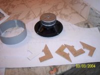
🙁Btw, i've developed all the surfaces required to cut the PVC.
6" at an angle of 45d for the woofer mount and another for a 4"cylinder that intersects the 6"PVC with their axis perpendicular... brushing up my engineering drawing skills...😀😛
ajju
Have u tried using some thing like a bessel allignment, which might give u a better phase response, ofcourse at the expense of a steep roll off.
Hey Ajju,
You have any doco I can read up on, for the bessel alignment & the "state variable" filters. Did'nt know it had a better phase response. And, how come the roll-off is steeper. If it is a 4th order won't they all roll off at 24db/octave.
I'm using an Audiolab & a Cambridge audio for amps.
Cheers,
sunil
Sunil,
This should interest you..😀
www.rane.com/note147.html
This will provide technical details of how the three topologies compare. Linkwitz, bessel and butterworth.
References to the famous ESP site.
http://sound.westhost.com/project09.htm
http://sound.westhost.com/project09.htm
The above implementations are for linkwitz-riley arrangement.:q
http://www.maxim-ic.com/appnotes.cfm/appnote_number/1762/ln/en
Provides some info on state varible filters and some tools to design them.
Thanks
ajju
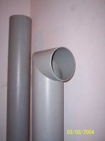
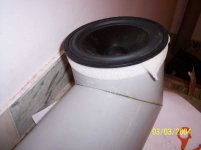
So, i've finally managed to cut and glue the PVC to form the main unit...but there was another problem...the PVC ID and the VIFA's dont match...to worsen the situation, the P17 mounting holes come exactly on the PVC, so cant fasten them with screws...so
had to figure out a way of mounting them...Looks neat...still to find out how well the coupling is and are there any air leaks at the joints....
Pictures of first unit coming up tomorrow...🙂
😀
ajju
had to figure out a way of mounting them...Looks neat...still to find out how well the coupling is and are there any air leaks at the joints....
Pictures of first unit coming up tomorrow...🙂
😀
ajju
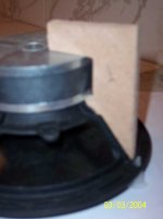

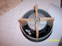
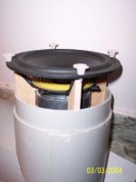
The woofer completely mount on the PVC...
the woofer is held by pressure through the inner gasket, and the clamps.
A piece of foam acts as a seal at the edge where the PVC meets the woofer frame..!!
Comments are welcome from all structural experts..(well infact everyone...) on the strong and weak points of mounting the woofer this way...!
the woofer is held by pressure through the inner gasket, and the clamps.
A piece of foam acts as a seal at the edge where the PVC meets the woofer frame..!!
Comments are welcome from all structural experts..(well infact everyone...) on the strong and weak points of mounting the woofer this way...!
Attachments
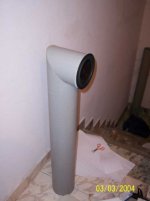
Ajju,
Super job. How are you going to load the pillars at the bottom ?
Thanx for the links. Yup, I had read these before, just did'nt remember them by name. The state variable is a little complicated & I'm not sure I want variable filters. I've been trying out different values for the baffle diffraction & have the various pairs of resistors in hand for testing.
Regarding the crossover freq. from woofer to mid, I want all the baffle diffraction correction to happen in one unit, the mid, rather than spread it over the woofer as well. Right now the diffraction is spread from around 210hz to just above 3000. The crossover for the woofer to mid is 200hz & mid to tweeter is 3100hz.
BTW I'm using BB2134 for the opamps. Guess what NE5532's are available in SP road for Rs. 15/- a piece.
Cheers,
sunil
Bonus picture....
Stuff that i have at my dorm..😀
The one with the grill is a chip amp..
a stereo pair...the grey unit next to it is its power supply...
farther away(the unfinished one lying on the floor) is the speaker i'm doing for my PC..!
its a powered unit with the amp mounted inside the enclosure.
amp is a ChipAmp based on a TDA device. The driver is a JBL 4"
And the one without a driver...finished in black..is a TL
http://www.diyaudio.com/forums/showthread.php?s=&threadid=19574
based on the same JBL drivers...(guess where the drivers are now..🙂)
All done in PVC...
Ok question time...
Can some one suggest me a good method of finishing PVC...
I used normal gloss paint, but the places i had sanded showed up to be rough. how to get around this...?
😀
ajju
Attachments

- Status
- Not open for further replies.
- Home
- Loudspeakers
- Multi-Way
- P17WJ and D27TG into a floorstander-advice.