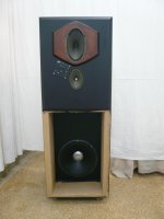
I'm not going to introduce myself as a loudspeakers expert... This project was a long trial and error procedure. I have them fully functional for a while so I don't seem to get motivated to finalize some details regarding aesthetics. Starting this thread might help to overcome procrastination...
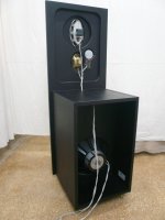
So here you are, open baffles -H frame for the bass- 4 way, 5 drivers together with a rear firing tweeter. Vintage alnico, rare but inexpensive. Even for the 15" Tesla woofers, I was lucky enough to find the last pair forgotten on the self of a local store. 270 euro pick up.😛 Total project budget around 700 euro complete! Sensitivity is 94dB/W/m. Dimensions H/W/D 150/55/55 cm.
It all started from the famous Lampizator P17 aka "Endorphin". Simple and impressive within its limitations. It is well described here: Greencones What Troels Gravesen missed by using his OB9 model for the bass was a huge peak at 100-120Hz because of the deep U shape design. My efforts to cure all these issues resulted to a loudspeaker that has very little to do with the original design, thus the funny nickname. From endorphin, the essence of joy to oxytocin, the essence of maturity. OK, I could find a better name...
It is unlikely anyone to have these drivers at hand to build it but this thread is mostly about inspiration and amusement. I'll describe how I built them. I didn't use any calculations or simulations. I decided crossover points roughly by the drivers' size and then measuring frequency response on and off axis together with impedance to avoid any fatal mistake. I can tell I enjoyed it very much!
Attachments

Nice woodworking.
Is that rear firing tweeter the little ribbon film by Fostex?
It is the Monacor rbt-96, ribbon magnetostatic. Everything is going to be explained.
Thanks for the comments! Here are more details for the drivers and the crossover.
The woofer: Tesla ARM 9408. Simply put, a beast! Qts=0,25 BL=21 T=1,35. In the original 50 cm deep U frame it was a disaster! There is no crossover that could tolerate this. Eventually, I followed the teachings of M.J.King and moved to H frame. Still not a perfect fit for such a low Qts. For this I used the baffle step compensation from Troels Gravesen open baffle projects. This allowed to move the peak from 100Hz to 50Hz where instead of being annoying it sounds very pleasing I can say! Cut at 200Hz.
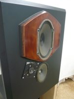
The midrange: Isophon P1526 oval, equivalent to a 8" round. But it has a different dispersion pattern than round. on the vertical axis is more like a 26 cm and on the horizontal like a 15 cm. It was meant for a fullrange in its days but no, even restricted from 200-2500Hz it asks for additional correction with a notch filter at 2kHz. I agree with Planet10, it sound awesome! I feel it introduces an amount of second order distortion but it's not like when it comes from an amp which I don't like. But coming from a driver is very nice! From here, a tweeter could take on but I didn't like the transition from 8" to 1". So another driver to fill the gap.
The lower treble: Grundig multi oktav 17x12 cm. This was the trickiest part! Don't ask how I managed the crossover. Only thing I can say is that the "naked" frequency response is missing a part of the final response. Go figure! That said, it does great job to match the big oval to the tweeter. This driver set the total sensitivity of the loudspeaker.
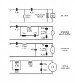
The tweeter: Initially, I used Isophon HM10. Very good if you ask me, but only from 10-15kHz. Off axis it was leaving a gap from 5 to 10kHz. Later I managed to put my hands no a nice pair of JBL LE26. I redesigned the crossover and it blends very well with the other drivers.
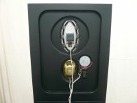
At some point I thought to try a rear firing tweeter. I chose the Monacor RBT-95. It has a ruler flat impedance across the audio band so it doesn't interfere with the crossover properties. It could be replaced with a 8 ohm resistor. Moreover, in the particular circuit it goes lower than the JBL which is welcome since the grundig does not go that high to the back as to the front. Testing with or without is as easy as masking it with a piece of paper. I couldn't see any measurable difference but it does something to the sound that I like.
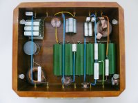
In the pictures you can see the story of the evolution in brief. I didn't even had a router back then! As for the crossover, I measured horizontal dispersion to pick the cutting points and then got myself a handful of cheap coils and caps and started trying every possible combination. I was measuring FR and impedance after every change. Once I got an even response on and off axis, I was sure it was OK ... at least for me. The final implementation was done with old soviet caps chosen for cost/value and a mix of coils. I kept in plce the cheap ones where it wouldn't matter. Power dissipation is not an issue, this loudspeaker can do 2w continuous, 4W peak. Ears get fried much earlier, I'm listening to sub watt levels. I did use two low DCR coils where it was calling for that.
The woofer: Tesla ARM 9408. Simply put, a beast! Qts=0,25 BL=21 T=1,35. In the original 50 cm deep U frame it was a disaster! There is no crossover that could tolerate this. Eventually, I followed the teachings of M.J.King and moved to H frame. Still not a perfect fit for such a low Qts. For this I used the baffle step compensation from Troels Gravesen open baffle projects. This allowed to move the peak from 100Hz to 50Hz where instead of being annoying it sounds very pleasing I can say! Cut at 200Hz.
The midrange: Isophon P1526 oval, equivalent to a 8" round. But it has a different dispersion pattern than round. on the vertical axis is more like a 26 cm and on the horizontal like a 15 cm. It was meant for a fullrange in its days but no, even restricted from 200-2500Hz it asks for additional correction with a notch filter at 2kHz. I agree with Planet10, it sound awesome! I feel it introduces an amount of second order distortion but it's not like when it comes from an amp which I don't like. But coming from a driver is very nice! From here, a tweeter could take on but I didn't like the transition from 8" to 1". So another driver to fill the gap.
The lower treble: Grundig multi oktav 17x12 cm. This was the trickiest part! Don't ask how I managed the crossover. Only thing I can say is that the "naked" frequency response is missing a part of the final response. Go figure! That said, it does great job to match the big oval to the tweeter. This driver set the total sensitivity of the loudspeaker.
The tweeter: Initially, I used Isophon HM10. Very good if you ask me, but only from 10-15kHz. Off axis it was leaving a gap from 5 to 10kHz. Later I managed to put my hands no a nice pair of JBL LE26. I redesigned the crossover and it blends very well with the other drivers.
At some point I thought to try a rear firing tweeter. I chose the Monacor RBT-95. It has a ruler flat impedance across the audio band so it doesn't interfere with the crossover properties. It could be replaced with a 8 ohm resistor. Moreover, in the particular circuit it goes lower than the JBL which is welcome since the grundig does not go that high to the back as to the front. Testing with or without is as easy as masking it with a piece of paper. I couldn't see any measurable difference but it does something to the sound that I like.
In the pictures you can see the story of the evolution in brief. I didn't even had a router back then! As for the crossover, I measured horizontal dispersion to pick the cutting points and then got myself a handful of cheap coils and caps and started trying every possible combination. I was measuring FR and impedance after every change. Once I got an even response on and off axis, I was sure it was OK ... at least for me. The final implementation was done with old soviet caps chosen for cost/value and a mix of coils. I kept in plce the cheap ones where it wouldn't matter. Power dissipation is not an issue, this loudspeaker can do 2w continuous, 4W peak. Ears get fried much earlier, I'm listening to sub watt levels. I did use two low DCR coils where it was calling for that.
Attachments
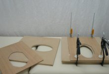
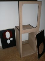


Things left to do... I need to make a new face plate for the tweeter to match it physically with the rest of the drivers. Any ideas are welcome. Also, I need to finish the bass section. I'm thinking of wood veneer or something. Measurements seem OK as is. I do have a few simple measurements to post but it takes some mental preparation to follow this. I'll explain it in a separate post.
It is the Monacor rbt-96, ribbon magnetostatic. Everything is going to be explained.
How do you find the sound of the Monacor ribbon/magnetostat?
I have wanted to try that model for a while
About measurements
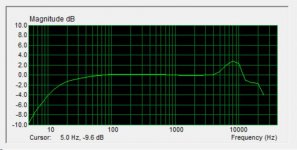
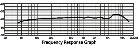
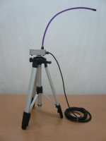
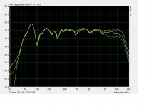
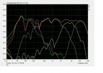
I have a good amp and soundcard. But my mic is a cheap diy. I don't feel like spending money for this just to use it in a few projects. What I realized is that all big brands actually use similar cheap capsules providing a calibration file for correction. And these capsules fall to just a few categories regarding frequency response. Long story short, I measured some tweeters like the above mentioned JBL and Monacor which are known to be reasonably flat and found that mine looks like the third pic. Next step was to find a calibration file from a commercial product and apply it. I had to make some minor changes to the file to get a flat response with my mic. See fourth pic. This is not a text book approach and does not ensure much, let alone +/-1dB accuracy. But I think it works well to have a look at crossover points and phase integrity. Suggestions on this are welcome.
Moreover, all measurements were taken indoors with all phase cancellations coming with that. Please keep this in mind and bear with me.
Attachments

How do you find the sound of the Monacor ribbon/magnetostat?
I have wanted to try that model for a while
I had tried it in an early phase as the main tweeter but everything was not refined then so I feel I've not been fair to that. And I don't recall much of it now, to be honest. At its present duties I think its character does not affect the sound. It is there to add reflections from the wall which makes for a nice sound stage.
Measurements
Simple things! Measurements were done with the mic at 1 m distance, ear level -right between the two ovals. Nothing is normalized. First pic is frequency response on axis. Red is combined FR together with individual drivers. For the woofer the purple curve is captured as said above. The green one is near field with level adjusted to match the rest. Next pic is horizontal dispersion at 0, 30 and 60 deg. Impedance is following with a min 3,1 ohm at 1kHz.
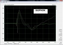
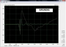
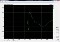
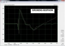
The rest is step response, even more idiosyncratic... Combined and individual drivers compared to combined. I thought this was useful to check.
Simple things! Measurements were done with the mic at 1 m distance, ear level -right between the two ovals. Nothing is normalized. First pic is frequency response on axis. Red is combined FR together with individual drivers. For the woofer the purple curve is captured as said above. The green one is near field with level adjusted to match the rest. Next pic is horizontal dispersion at 0, 30 and 60 deg. Impedance is following with a min 3,1 ohm at 1kHz.
The rest is step response, even more idiosyncratic... Combined and individual drivers compared to combined. I thought this was useful to check.
Attachments


Thank you for sharing this, really nice diy job!
Can you tell us dimensions of your listening room and placement of speakers and listening position.
Can you tell us dimensions of your listening room and placement of speakers and listening position.

Thanks a lot! Listening room is 6,4x4,2m, 3m high. Speakers are placed about 1m from rear wall and 80cm from sides. They are toed in some 20 deg. Listening position is at ~2,5m. A completely untreated room, meant to be a temporary station for my magic bus before financial crisis, before IMF, before corona... I'm very happy I went for open baffles. Nothing rattles at ear shredding levels!
- Home
- Loudspeakers
- Multi-Way
- Oxytocin