Hello guys, I'm working on a loudspeaker protection design based on UPC1237. In it's datasheet there isn't provided any example of overload circuitry.
Designing such a circuitry isn't an easy task because there are lot of variables that should be considered in it since different amps work with different voltages and etc..
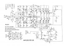
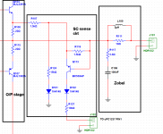
I have attached the M9 Amplifier schematic from "Analog Metric". this design benefits from upc1237 + overload detection circuit.
I want to know if it's possible to use and adopt the overload detector circuitry introduced in the M9 amp for another amplifier? say a MOSFET one like the Bora jagodic's designs.
Designing such a circuitry isn't an easy task because there are lot of variables that should be considered in it since different amps work with different voltages and etc..
I have attached the M9 Amplifier schematic from "Analog Metric". this design benefits from upc1237 + overload detection circuit.
I want to know if it's possible to use and adopt the overload detector circuitry introduced in the M9 amp for another amplifier? say a MOSFET one like the Bora jagodic's designs.
Attachments
I' m bit confused about were those lines (3 red on the left & 1 red going down) go? Can you pls post photos of PCB & explain it.
Last edited:
Those lines represent the power amplifier output stage itself, not the protection circuit.I' m bit confused about were those lines.....
If you follow the chip's application notes, you will get a better idea of how its adapted to various power amplifiers and the proper specification of values to adapt to your application if suitable, and not some other amplifier with different ratings. NEC - datasheet pdf
@KatieandDad, with R107 I'm guessing it sets trigger threshold. This combination sets it around 3A, IINM (0.6/0.22 * (16.5/15))
@Andreas, that circuit would trigger at a much lower threshold, would there not be a potential divider to adjust the threshold?
Have done some limited testing on the first circuit (the bad one) in an amp I am building. I agree that intuitively sensing current through both Re is better but even the other one worked. Haven't seen a situation where the circuit did not trip, including a shorted PNP transistor or a non-sensed pair shorting out. In every case the protection tripped.
It is a universal scheme. Threshold to arrange an additional resistor in parallel included C1.Calculation resistors watch SOA output transistors.@Andreas, that circuit would trigger at a much lower threshold, would there not be a potential divider to adjust the threshold?
Current sensor signal takes two output transistor - higher reliability.Have done some limited testing on the first circuit (the bad one) in an amp I am building. I agree that intuitively sensing current through both Re is better but even the other one worked. Haven't seen a situation where the circuit did not trip, including a shorted PNP transistor or a non-sensed pair shorting out. In every case the protection tripped.
Dear all, Thanks for the prompt replies.
How can I apply this ckt in chip amps(LM1875,3886, e.t.c.)?
@ Andreas AVM
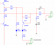
Pls see attch., correct me if I'm wrong in understanding-
VT1, VT2 - o/p stage power transistors
VT3, VT5 (part no.?) - over load / S.C. current sense circuit.
@Ian Finch
I've built DC protection ckt using upc1237 & want to add overload / SC current sense capabilities. Being mathematically challenged I got stuck with formulas shown in datasheet.😱 Surprisingly the ckt worked flawlessly!
How can I apply this ckt in chip amps(LM1875,3886, e.t.c.)?
@ Andreas AVM
Pls see attch., correct me if I'm wrong in understanding-
VT1, VT2 - o/p stage power transistors
VT3, VT5 (part no.?) - over load / S.C. current sense circuit.
@Ian Finch
I've built DC protection ckt using upc1237 & want to add overload / SC current sense capabilities. Being mathematically challenged I got stuck with formulas shown in datasheet.😱 Surprisingly the ckt worked flawlessly!
Attachments
Last edited:
The project below is in response to your question (you will need to register there if you want download the DP0105 project):
DP0105 - Amplificator audio stereo Hi-Fi 2x200W cu MOSFET - "donpetru" projects - Comunitatea Tehnium Azi
You see in that project a solution that deserve implemented and explored.
Good luck
DP0105 - Amplificator audio stereo Hi-Fi 2x200W cu MOSFET - "donpetru" projects - Comunitatea Tehnium Azi
You see in that project a solution that deserve implemented and explored.
Good luck
Yeah, right, the sensor output to file for PIN1.
R6 - 47K, and the rest, according to the service manual in upc1237.
For LM1875,3886 current sensor is not needed, it is already integrated into the chip.
R6 - 47K, and the rest, according to the service manual in upc1237.
For LM1875,3886 current sensor is not needed, it is already integrated into the chip.
Silly me😱, I just realized that chipamps have built in protection, after I posted my comments.Above all the response time would be faster than any external relay circuit.
Last edited:
It's not in english.The project below is in response to your question (you will need to register there if you want download the DP0105 project):
DP0105 - Amplificator audio stereo Hi-Fi 2x200W cu MOSFET - "donpetru" projects - Comunitatea Tehnium Azi
You see in that project a solution that deserve implemented and explored.
Good luck
Is there an english translation?
L100 and R111 for the L||R section of the Thiele Network are very high.Dear all, Thanks for the prompt replies.
How can I apply this ckt in chip amps(LM1875,3886, e.t.c.)?
@ Andreas AVM
Pls see attch., correct me if I'm wrong in understanding-
VT1, VT2 - o/p stage power transistors
VT3, VT5 (part no.?) - over load / S.C. current sense circuit.
@Ian Finch
I've built DC protection ckt using upc1237 & want to add overload / SC current sense capabilities. Being mathematically challenged I got stuck with formulas shown in datasheet.😱 Surprisingly the ckt worked flawlessly!
Have you rejected normal values for this amplifier?
I've not implemented anything from the above mentioned ckt. I normally go by values mentioned in data sheets.
Original ckt is from uPC1237 Amplifier/Speaker Protection Module - DIY AUDIO BLOG, AUDIO WORKSHOP
Original ckt is from uPC1237 Amplifier/Speaker Protection Module - DIY AUDIO BLOG, AUDIO WORKSHOP
Regarding to the post#6,It is not very reliable scheme. Bad Swiss watches ...
Reliable scheme in the application:
can anyone provide some useful component values please? It would be even more reliable if values given for an example scenario.
For any application need?Regarding to the post#6,
can anyone provide some useful component values please? It would be even more reliable if values given for an example scenario.
That's right to question. The whole basis of an overload protection circuits is that it must be adjusted precisely for the output stage it must protect. There are no typical values to try except by the given uPC1237 datasheet and application notes....For any application need?..
If someone claims their arrangement "works" by shutting down when the output is shorted, it means nothing if it is tripping at some fraction of the amplifier's rated power output. Unless the trip current is measured by some means, you can't know if it works perfectly or not without having followed the datasheet directions for your amplifier's design and output specifications.
The amplifier power rating is the basis of the values to be calculated which should maintain the output devices within their datasheet SOA curve limit at all times. Otherwise, you either have no protection or too little power output.🙁
I agree. Current sensor should be considered for a particular output stage. uPC1237 only reads the signal and makes the defense.
This scheme is not correct. It will not operate reliably for a short circuit of the output.I've not implemented anything from the above mentioned ckt. I normally go by values mentioned in data sheets.
Original ckt is from uPC1237 Amplifier/Speaker Protection Module - DIY AUDIO BLOG, AUDIO WORKSHOP
- Home
- Amplifiers
- Solid State
- Overload detection circuit for UPC1237