hi folks,
a noob question here (should that not be clear from what follows )
)
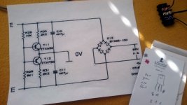
I have hooked up a cheap 48V supply to a couple of TDA7293 amps through a DIY voltage divider to get +/-24V:
When I don't hook up the TDA's, I get a nice +/-24V, but as soon as the TDA's are connected, the led on the power supply immediately starts blinking, indicating that the overcurrent of shortcut protection kick in, I guess.
Which beginner's mistake did I make?
Thanks in advance!
a noob question here (should that not be clear from what follows
)I have hooked up a cheap 48V supply to a couple of TDA7293 amps through a DIY voltage divider to get +/-24V:
An externally hosted image should be here but it was not working when we last tested it.
When I don't hook up the TDA's, I get a nice +/-24V, but as soon as the TDA's are connected, the led on the power supply immediately starts blinking, indicating that the overcurrent of shortcut protection kick in, I guess.
Which beginner's mistake did I make?
Thanks in advance!
Dear noob,
You seem to have a soft neutral which is not suitable for loads with high current draw, which is why the splitting fails. You may try the following to patch things up:
1) Find a 24V output from your SMPS (if it exists) and use the same as the mid point.
2) Operate the amplifiers from a single supply.
3) Design and build another power converter with high current capability to properly split the 48V to +/-24V.
All the best.
thanks for your replies rayma and nv,
for info, this is where I got the idea:
Dual supply audio amplifier kit powered from single power supply - YouTube
However, my TDA boards are designed for an AC input (first thing the supply voltage encounters is a rectifier bridge). What if I connect the supply voltage after the rectifier bridge?
for info, this is where I got the idea:
Dual supply audio amplifier kit powered from single power supply - YouTube
However, my TDA boards are designed for an AC input (first thing the supply voltage encounters is a rectifier bridge). What if I connect the supply voltage after the rectifier bridge?
Unfortunately, whichever way you connect things, the split neutral would still walk away in due course, because of the DC errors in the system. Now, the above video demonstrates the circuit only for a brief period, cleverly avoiding the long-term imbalance issue altogether!
Please note that this type of arrangement is also used in the half-bridge SMPS and the resulting walkaway of the pseudo-neutral has also been well-documented in literature. However, the SMPS manages to get away with the cheap arrangement due to the low primary current draw (step-down) and a flux-walking capacitor in series with the transformer winding.
Your best bet is to try and find a 24V point on the SMPS board somehow, if one exists. Alternatively, you can convert the SMPS to +/- 48V (at same power), if the transformer secondary winding is centre-tapped.
this worked for me for chip amp, to split the power supply into symmetrical
post #9
hacking the power supplies
done it many times, but not with classD
post #9
hacking the power supplies
done it many times, but not with classD
That's buffering the neutral using active electronics, which is definitely an option, but the OP seemed to suggest passive. As long as it's balanced, the current into the mid-point will be zero and the buffer will work, but if somehow unbalanced, will it come back to null point? And how many amperes can that do?
It could be done properly though.

It could be done properly though.
Last edited:
completely wrong question, since the circuit only creates middle ground, current does not flow through it..current flows through the amplifier...
Well, let me rephrase the question for you:
The capacitors get unbalanced by the speaker current flowing into the midpoint (picture). Aren't the emitter followers then supposed to balance them again by conducting appropriately? And since these balancing currents (amperes) are now limited by the collector resistors of the transistors, don't they also limit the balancing performance of the arrangement?
By the way, passive methods are guaranteed to fail (at least in the long run) and some form of active control would be necessary in my opinion.

dc current does not flow through the caps
amp has no dc on the output, there is no dc current flowing through the speaker like you draw
most amps have dc protection on the output, and if they do not, they have no dc on the output
some have dc servo
amp with dc on the output is malfunctioning
dc going through speaker misplaces the voice coil out of the magnet gap
heats the coil and eventually destroys the speaker
I do not get the picture you draw, its utter nonsense
that would never work
I am outa here
I don't think I said "DC" anywhere, as most people in this forum (including myself) already know (without anyone having to tell them) that the load current is AC.
Capacitor unbalancing is a dynamic/instantaneous thing that occurs as load current flows through the speakers. The picture (attached) shows the imbalance caused in a 2 x 4700uF capacitor neutral by a 5A load current at 50Hz frequency (bass).
Now, Adason, if you still think such imbalances are only due to DC, then I don't think I can convince you otherwise. Also, the fact that you didn't get what I drew does not mean it's utter nonsense, maybe it was truly beyond your reach !
Now, just to give an idea of what you've said until now, Adason (no offence):
In post #11, you say the following:
And then in #14 you say:
In post #11, you say the following:
adason said:current does not flow through it.. current flows through the amplifier
And then in #14 you say:
adason said:dc current does not flow through the caps..amp has no dc on the output, there is no dc current flowing through the speaker..I do not get the picture you draw, its utter nonsense.. that would never work ...I am outa here
Last edited:
dc flows inside the amplifier through output (and other stages) transistors
there is no dc going to the speaker (only ac)
my statements are both correct and not in controversy with each other
you are totally lucking any knowledge how amplifiers work
I am placing you in ignore list from now
there is no dc going to the speaker (only ac)
my statements are both correct and not in controversy with each other
you are totally lucking any knowledge how amplifiers work
I am placing you in ignore list from now
Peace guys
Interesting content!
Passive is not a must for me, this circuit is just the first I encountered. So other splitting circuits are definitely an option.
Unfortunately the SMPS has no 24V output; only 2 leads.
NV: “2) Operate the amplifiers from a single supply.”: do you mean hook up the 0 and 48V to the ac inputs of the amps and not connect the 0 of the amps?
- Home
- Amplifiers
- Class D
- overcurrent protection