So I have three starting points:
20 aligned verticals:
25 offset verticals
42 aligned horizontals
Based on the simulations, the 4Khz point appears to be a driver limitation. What is the order of priority to choose the best scenario? The red line on the Power & DI chart, the vertical directivity or the horizontal directivity? I don't have all three in the same package.
The ‘best scenario’ is the horizontal arrangement and crossed to a tweeter at 4khz. Without a tweeter, this alignment would be an exercise in confirming what’s already practical line array behavior.
As I’ve mentioned before, I applaud the folks who challenge the physical limitations with EQ and DSP to achieve great results in an as much as the hundreds that still climb Everest every year for the experience.
As I’ve mentioned before, I applaud the folks who challenge the physical limitations with EQ and DSP to achieve great results in an as much as the hundreds that still climb Everest every year for the experience.

With frequency shading I was able to soften the red line only in the offset model. Just using inductors. I didn't have success with the others.Just wish it was a bit less unbalanced at ~4K and ~11K
| no shading | with shading |
Last edited:
Maybe it would even be good even with this decreasing curve, after all the human ear doesn't hear in a flat way, as Fletcher and Munson said. It'll be fun.
With frequency shading I was able to soften the red line only in the offset model. Just using inductors. I didn't have success with the others.
View attachment 1328797 View attachment 1328799 no shading with shading
That's quite narrow both horizontally and vertically as far as direct sound goes! Easy to be outside of a good listening position.
The DI shows it's illuminating the room more even though. As long as there are reflective walls etc. (Edit: just noticed the DI numbers are quite high)
Even though the DI looks much
The graph with the filters on would have a very small vertical window of good sound. The DI (red line) shows it's starting to beam from 2.5K upwards (higher DI numbers). So the listening window would be quite small for having good sound. Get out off that window and you'd loose a lot, no good balanced sound anymore.
I didn't like it either. I want a good listening position for at least two people to sit. Vertical narrowing is more acceptable than horizontal narrowing. So, the first model, with the drivers mounted aligned and vertically, looks more interesting, but needs to be improved from 3Khz onwards.
Purpose of VCAD Diffraction tool is to simulate directivity at low frequencies; baffle step/loss on-axis and LF directivity of boxed and open concepts in case LF directivity is not measurable. Never try to design mid...high frequency equalization with simulated directivity because it is very inaccurate.
P.S. Equalization for straight line array without power tapering is difficult to design, and also bad concept imo because response depends on distance.
P.S. Equalization for straight line array without power tapering is difficult to design, and also bad concept imo because response depends on distance.
For anyone curious about frequency responce of straight full range arrays at varying distances and height, look up this post in the thread by @ra7 : https://www.diyaudio.com/community/...ray-using-vifa-tc9.284371/page-7#post-4584879
I don't quite agree with the conclusion of the previous post as both simulation and actual measurements have shown me something different. Granted you don't try to listen too close.
I don't quite agree with the conclusion of the previous post as both simulation and actual measurements have shown me something different. Granted you don't try to listen too close.
My intention is to point out my error so that no one reads this topic and follows the wrong path I took.
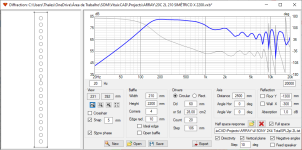
Intrigued by the bad simulations, I left the project for later. Now that I decided to delete the old data and start simulating again, I discovered where I went wrong. As can be seen in the first post, I don't know why, I used 20 drivers in the diffraction tool. Use just one and the program will take care of simulating the different positions defined with the driver's layout tool.
Wrong way ("Kids, don't do this at home!"):
Right way:
As proposed by kimmostro, because of the different shape of the drivers I have:
Notably SPL, CTA-2034, GD&PHASE and DIRECTIVITY (HOR) charts are now as expected. It wasn't for lack of warning, but the package provided by nc535 here helps a lot in your first contact with VituixCAD.
I thank everyone for their attention and I apologize for the misunderstanding.
Attachments
Last edited:
- Home
- Loudspeakers
- Full Range
- Oval driver line source