Here is something for all you Academics, Self Professed Experts & Nay Sayers to puzzle over. As usual, some without a careful look will tell me it doesn't work. Too many Monday morning quarter backs here!
If you think it will work, then why. But better be able to recommend tube types. It matters.
Some may have seen this already. I posted it elsewhere a few years ago.
Good Luck to all!! And don't tell me why YOU would not do it. I don't care!
If you think it will work, then why. But better be able to recommend tube types. It matters.
Some may have seen this already. I posted it elsewhere a few years ago.
Good Luck to all!! And don't tell me why YOU would not do it. I don't care!
Attachments
Last edited by a moderator:
Here is something for all you Academics, Self Professed Experts & Nay Sayers to puzzle over. As usual, some without a careful look will tell me it doesn't work. Too many Monday morning quarter backs here!
If you think it will work, then why. But better be able to recommend tube types. It matters.
Some may have seen this already. I posted it elsewhere a few years ago.
Good Luck to all!! And don't tell me why YOU would not do it. I don't care!
You sound a bit touchy and combative, IMHO. But anyway, I'll bite since I like a good thought exercise.
I think it will work. My strategy would be to choose an output tube that passes the desired bias current with some positive idle grid voltage. Then I would choose a tube as the driver that would produce that bias grid voltage while feeding the required idle grid current to the output tube with the driver tube grid at ground potential. Tubes would have to be chosen carefully to make it all work.
And I know you don't care but I wouldn't do this since DC balance would be dependent on tube characteristics being very matched and consistent both when new and throughout service life.
Last edited:
Thankyou for responding. You are on the correct track. Balancing the output for both AC & DC is same as any other PP amp. I will let this run for a while & see what else comes in.
I find the diy group very negative, much of it is won't work or worse. These folks would starve in sales. But they will tell us they would not do that either. Progress results when people push the envelope. Not by dragging their feet.
I find the diy group very negative, much of it is won't work or worse. These folks would starve in sales. But they will tell us they would not do that either. Progress results when people push the envelope. Not by dragging their feet.
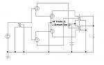
Why not crossing the connections for a change, repeating is dull.
Mona
Not sure what you mean. Pls explain.😱
Why not crossing the connections for a change, repeating is dull.
Mona
Do you mean change "NFB" for "PFB" ?
Funny !
I find the diy group very negative, much of it is won't work or worse. These folks would starve in sales. But they will tell us they would not do that either. Progress results when people push the envelope. Not by dragging their feet.
I sympathize somewhat. I don't know how many times I have come here and asked "How do I accomplish X" and I get the answer "Don't do X, Y is better."
Some of the time, I'm well aware that X isn't the best approach but I want to just think about how it would work and explore the idea. Other times, I just want to do something that I've never seen before just to see if I can make it work.
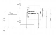
The J Stewart circuit is acting much like a pentode UL stage (deriving N Fdbk via the UL tap). But requires a zero bias (or positive bias) output tube (or a positive bias input tube with a resistor pull-down load added at the driver cathode), as SpreadSpectrum said, with a miraculously selected input tube. Some DC idle fixups could fix that, so more tubes could work. Otherwise, DC stability rather a concern.
One needs to be careful about the relative Mu of the driver tube versus the output tube, could fry the output grid if the driver Mu is too high. Although, too high a driver Mu would probably prevent them from drawing much grid current to start with. (being triodes)
Mona's circuit is providing positive Fdbk via the UL tap. As long as it doesn't go past unity loop gain, it would boost the gm effectively of the output tubes. Same DC stability fixes needed.
Last edited:
But requires a zero bias output tube (or a positive bias input tube with a resistor pull-down load added at the driver cathode), as SpreadSpectrum said, with a miraculously selected input tube.
I decided to see if I could find a magic combination. I set up an 841 as the output tube at 200V and 50mA. (10W) This draws 7.5mA in the grid at idle at +24V.
I looked around a bit to see if there was a tube that would need -24V of bias at 200V and 7.5mA. All I could come up with was 6L6 triode connected. Seems like overkill but it would all work out I think.
"I don't know how many times I have come here and asked "How do I accomplish X" and I get the answer "Don't do X, Y is better." "
Hehe... I couldn't wait to come up with a "better" solution:
Put CCS loads on the driver cathodes (from -V), with negative bias output tubes. Then the driver Mu must be satisfied at all times, giving the whole stage Mu x(1/fractionUL) gain. (Oh, and -Vbias on the center tap of the input xfmr) (also assuming the output tubes have higher Mu than the driver tube, pentode outputs with fixed +Vg2 would work best. Or use Mona's approach with crossed UL to the output pentode screens for boosted gm.)
Last edited:
"I don't know how many times I have come here and asked "How do I accomplish X" and I get the answer "Don't do X, Y is better." "
Of course, I wasn't thinking of your comments when I said this, more the people who spend all of their time telling you that you are doing it wrong and offering no interesting insights. It gets tiring trying to justify an approach that you aren't even committed to but are just trying to explore.
Here is a hint. You will find tubes that will work in this cct right out of the box in RCA Receiving Tube Manual RC-14. That is around WW2. Without the artillery!
Most of those are now hoarded by the vintage guys. To do my work I picked some others, just as old.
Some folks here are pretty close to a working solution.
Most of those are now hoarded by the vintage guys. To do my work I picked some others, just as old.
Some folks here are pretty close to a working solution.
Here is a hint. You will find tubes that will work in this cct right out of the box in RCA Receiving Tube Manual RC-14. That is around WW2. Without the artillery!
Most of those are now hoarded by the vintage guys. To do my work I picked some others, just as old.
Some folks here are pretty close to a working solution.
Are you saying there is a pair of tube types that will work with a wide range of supply voltages? or is there a B+ we are shooting for?
I'd probably look at 811A or 812A for the power tube if I were building this, then work out the driver after I chose operating point and load impedance. I always wanted to build an amp with one of those tubes.
Some possibilities, direct drive tubes, all in one bottle:
6B5
25B5
25/6N6
6AC6
Might be able to find the individual sections used in those in other bottles. But maybe these were tested for section match-up in the single bottle. Would have to check the datasheets to see if they satisfy the zero volt input grid to output cathode requirement.
6B5
25B5
25/6N6
6AC6
Might be able to find the individual sections used in those in other bottles. But maybe these were tested for section match-up in the single bottle. Would have to check the datasheets to see if they satisfy the zero volt input grid to output cathode requirement.
Last edited:
Dynamic Drive: 25AC5G / 6AE5G 6P5G 76 37 6J5
https://frank.pocnet.net/sheets/127/6/6AC5GT.pdf
https://frank.pocnet.net/sheets/127/2/25AC5GT.pdf
https://frank.pocnet.net/sheets/201/6/6AC6G.pdf
https://frank.pocnet.net/sheets/201/6/6AC6GT.pdf
https://frank.pocnet.net/sheets/127/6/6AC5GT.pdf
https://frank.pocnet.net/sheets/127/2/25AC5GT.pdf
https://frank.pocnet.net/sheets/201/6/6AC6G.pdf
https://frank.pocnet.net/sheets/201/6/6AC6GT.pdf
Last edited:
Some possibilities, direct drive tubes, all in one bottle:
6B5
25B5
25/6N6
6AC6
Might be able to find the individual sections used in those in other bottles. But maybe these were tested for section match-up in the single bottle. Would have to check the datasheets to see if they satisfy the zero volt input grid to output cathode requirement.
Go to the head of the class immediately!! You must be an old guy like me.
For the 6AC6 I think you mean 6AC5. And the 25AC5 which is usually driven by a 6AE5. All cost too much now.
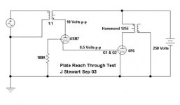
So I used a 6F6 much like a zero bias triode with G1 & G2 strapped together & found by experimentation that has a triode mu ~ 50. The driver is paralleled sections of a 6SN7. If you look at the triode mu of most audio pentodes & beam tubes they are in the range of 7 to 15. So the first triode needs to be meduim mu, the 2nd high. And all will look like a pentode.
I also did a 'Reach Thru' test on the 6SN7, refer to the attached. The measurement conforms 1/mu, nice to see for real!
But I did not do all this with the intention of building such an amp. I had long ago graduated from my slide rule & like any good HP employee I ran HP35, then HP67 & HP 71B with all the HPIL goodies. It was time to get some real simulation software so I bought Electronic Workbench Vers 5 to run in WIN95.
Curses, no pentodes, just any triode one could conceive of. And no obvious way to enter SPICE text files, sofar as I could see. What to do?
So I charged ahead & made my own models of pentodes using pairs of triodes. Just like we did here.
The other way round I use the voltage controlled voltage source for the triode & the voltage controlled current source for the pentode. All stuck to the proper plate rp.🙂
Attachments
6AC6 appears to be one also:
https://frank.pocnet.net/sheets/201/6/6AC6GT.pdf
https://frank.pocnet.net/sheets/201/6/6AC6G.pdf
I saw someone trying to use one of those dynamic duo type tubes in another thread.
Rip Van Winkle was in the family.
Can get 25AC5GT for $4 and 6AE5 for $6 here:
http://www.esrcvacuumtubes.com/vacuumtubes_tubelist_tubes_13CW4-90c1.html
Last edited:
I had never heard of that source, the prices do look good. The 6AC5GT at $10, a lot less than I recall.
I used Antique Electronic Supply a lot. There pricing looks somewhat higher today-
https://www.tubesandmore.com/search/node/6ac5
But I will pass for now.
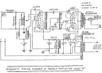
See attached a commercial amp using those kind of tubes. If you look at the pinouts they are a direct plug-in for the equivalent pentode. And in normal operation, no cathode bias resister is required.
I used Antique Electronic Supply a lot. There pricing looks somewhat higher today-
https://www.tubesandmore.com/search/node/6ac5
But I will pass for now.
See attached a commercial amp using those kind of tubes. If you look at the pinouts they are a direct plug-in for the equivalent pentode. And in normal operation, no cathode bias resister is required.
Attachments
- Status
- Not open for further replies.
- Home
- Amplifiers
- Tubes / Valves
- Outside the Box - Part ll All Triode UL PP Amplifier