Hello my nameis edwin olthuis
I am from holland.
I have aquired an built edison 60 amp from audion wich is in need of a restauration.
I have downloaded the instruction manual. I have already seen that the uotput transformers are the older ones wich have the 2 ohm tap.
Here is my question. The manual is not entirely conclusive regarding the secondary taps. B1 to B4.
First they tell that B1 is the 0 tap with the ground connection and that B3 isthe 4 ohm tap and B4 the 8 ohm tap.
Further on in the manual they state that B1 is the 8 ohm tap and B2 is the four ohm tap. B3 the 2ohm tap will no longer be present in future teansformers.
This sounds like a mixed up connection. But what are the real connections? Is B1 the 0 tap or is B4 the 0 tap.
Hopefully somebody has the answer.
I have added the specific parts of the instruction manual.
Regards edwin
Attachments
I would put a signal into the amp, and measure the AC voltage coming out of the transformer. Use an analog VOM, DVM produce random numbers on frequencies other than 50 or 60 hz. Except the $180 fluke RMS DVM which cannot see oscillation over 7 khz, so I don't suggest anybody buy one. Even a 5 kohm/v cheap AC VOM can make useful measurements at speaker impedances.
Higher AC voltages obviously are for higher impedance speakers. The speaker return terminal is inscruitable, perhaps DC resistance could tell you something. Resistance or AC out should increase from all other terminals to the speaker ground terminal.
Higher AC voltages obviously are for higher impedance speakers. The speaker return terminal is inscruitable, perhaps DC resistance could tell you something. Resistance or AC out should increase from all other terminals to the speaker ground terminal.
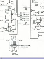
From your schematic, this amp doesn't have grounded speaker terminal nor global negative feedback. So you can connect B0 or B4 tap as speaker negative or 8 ohms positive. The out put phase will differ in both case.
If your PSE mean parallel the two channels into one with 2X power, yes you can do that. You can also bridge the two channel with this amp (no chassis ground on speaker terminal).
PSE normally means parallel single-end amplifier which this amp is not. If you plan to modify the circuitry and use this amplifies' push pull transformer, you will need to add parafeeding circuitry for PSE configuration or change the transformer in to one that support single end DC bias current.
If you want each channel to be PSE (Parallel Single Ended),
First, . . .you have lots to change in the input/invertor stage, and in the driver stage.
Then as suggested in the other posts, the output has to be either changed to Parafeed (add a plate choke) and a coupling cap; to drive the push pull transformer,
Or, add a SE (Single Ended) transformer.
In any case, you will also have to change the negative feedback, according to the other changes,
Or, you could wire the output tubes in Triode Mode, and not use any negative feedback.
If you simply parallel the 2 channels of push pull, you will not have PSE (Parallel Single Ended). There is no single ended to this amp as shown.
It will simply become a Parallel Push-Pull amp.
Last edited:
This is a good amp. Reconfiguring it as something else will spoil it's goodYou can configure this amp to pse mode wich i want to use.
Edwin
properties and be the polish equivalent of "******* in the soup". Don't.
To spare your efforts it would be better to throw it in the garbage bin !
( The stars above was inserted by censorship, it was a word for ejecting urine )
Last edited:
petertub,
I agree with you.
In my post # 7, instead of what I said, I should have said:
If you want a PSE (Parallel Single Ended) amp, then build one from scratch.
Do not modify the Push Pull amp you have to become PSE.
I agree with you.
In my post # 7, instead of what I said, I should have said:
If you want a PSE (Parallel Single Ended) amp, then build one from scratch.
Do not modify the Push Pull amp you have to become PSE.
From your schematic, this amp doesn't have grounded speaker terminal nor global negative feedback. So you can connect B0 or B4 tap as speaker negative or 8 ohms positive. The out put phase will differ in both cases
Look again J110 which connects to B4 is feedback, J111 which connects to B1 is ground.
Last edited:
Hello guys,
If you check audion.co.uk. Then you can see,and find the edison 60 ampkit. You can also find the complete instruction manual. If you read well, then you can see wich i already stated in the first post. That first they talk about B1 as the zeroohm tap and later they say that B4 is the zero ohm tap.
The zero ohm tap is grounded. So you have to take into account wich side is the zeroohm tap.
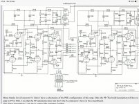
I think the schematic is not entirely right. In the schematic you see B4 on the side of A1 and B1 on the side of A5. But you can also see a picture of the output trannie, and in this picture you see B4 on 5he side of A5 and B1 on the side of A1
This is the connection wich i am going for.
And bye the way the amp is configurable to pse. Wich you can read in the instructions. The transformer isairgapped.
If you check audion.co.uk. Then you can see,and find the edison 60 ampkit. You can also find the complete instruction manual. If you read well, then you can see wich i already stated in the first post. That first they talk about B1 as the zeroohm tap and later they say that B4 is the zero ohm tap.
The zero ohm tap is grounded. So you have to take into account wich side is the zeroohm tap.
I think the schematic is not entirely right. In the schematic you see B4 on the side of A1 and B1 on the side of A5. But you can also see a picture of the output trannie, and in this picture you see B4 on 5he side of A5 and B1 on the side of A1
This is the connection wich i am going for.
And bye the way the amp is configurable to pse. Wich you can read in the instructions. The transformer isairgapped.
Attachments
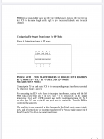
I'm not sure if you've missed the conversion instructions on the Audion's web-site. Here it is how you can make it into a 300B PSE. One of this kit's main advantage (besides its nice quality output) is its flexibility in converting in something else:
Edison 60 kit conversion to 300B
Edison 60 kit conversion to 300B
Last edited:
From your schematic, this amp doesn't have grounded speaker terminal nor global negative feedback..
Not true, both on the schematic and in the the kit's manual it is actually required to connect the output B1 to the ground (please double check the schematic)...
See page 6:
http://www.audion.co.uk/Kits/Edison%2060%20Manual%20ver1.pdf
Last edited:
- Home
- Amplifiers
- Tubes / Valves
- Output transformerquestion edison 60 amp